Supercharge Your Innovation With Domain-Expert AI Agents!

Built-in floating ball valve

A kind of floating ball valve, built-in technology, applied in the field of floating ball valve, can solve the problems of loose closing, short service life, inconvenient installation and use, etc., and achieve the effect of overcoming the tight closing

Active Publication Date: 2015-06-10
YANGZHOU DAYANG WATER SUPPLY EQUIP
View PDF7 Cites 0 Cited by
  • Summary
  • Abstract
  • Description
  • Claims
  • Application Information

AI Technical Summary

Problems solved by technology

The existing float valve is to separate the valve from the float, and the valve is controlled by the crank arm and the float outside the valve, which has the disadvantages of inconvenient installation and use, easy failure, short service life, etc. If it is closed according to the direction of water flow or water pressure of tap water, the direction of pressure of tap water is the same as the direction of opening of the valve plate or valve core, which is likely to cause the disadvantage of not being tight and easy to leak

Method used


Image

  • Built-in floating ball valve
  • Built-in floating ball valve

Examples


Embodiment 1

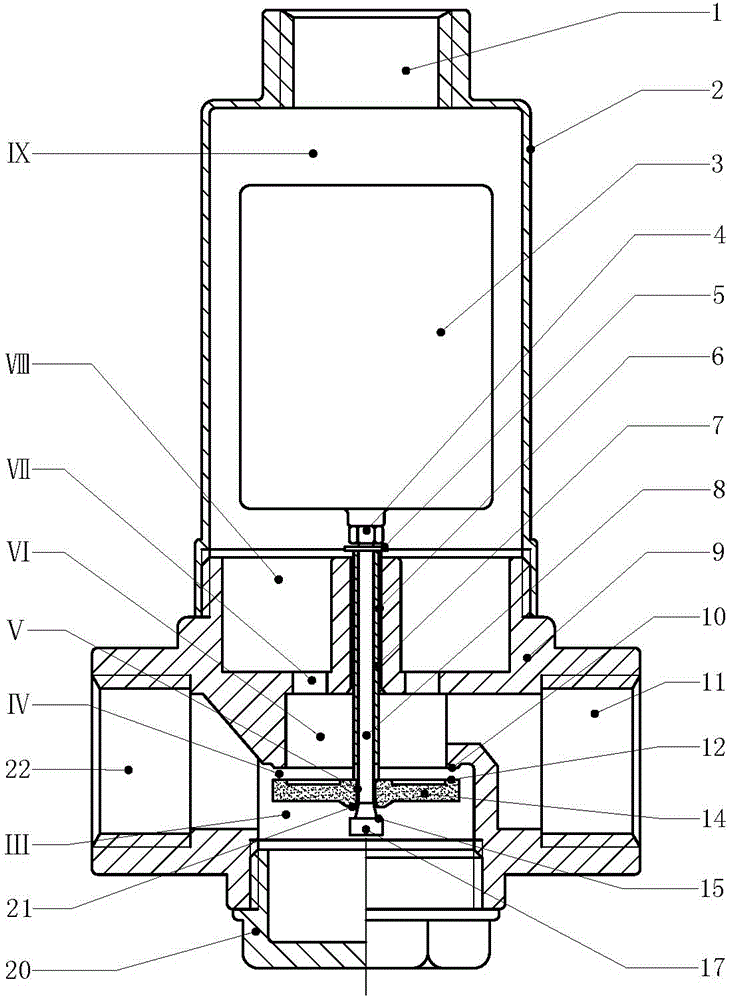
[0014] Embodiment 1 Attached figure 1In the shown embodiment, the first type of built-in float valve is mainly composed of valve body (9), main valve plate (14), pressure relief valve core (17), float ball (3) and valve housing (2). Among them, the valve body (9) has an upper valve chamber (Ⅵ), a lower valve chamber (Ⅲ), a center slideway (6) and a sealing surface a (10), an upper valve chamber (Ⅵ) and a lower valve chamber (Ⅲ) It is a cylindrical space, the upper valve chamber (Ⅵ) is above the lower valve chamber (Ⅲ), the section of the upper valve chamber (Ⅵ) is smaller than the section of the lower valve chamber (Ⅲ), and the sealing surface a (10) is on the top of the upper valve chamber (Ⅲ) ), the center slideway (6) is in the center of the top wall of the upper valve chamber (Ⅵ); the main valve plate (14) is a disc structure, and the main valve plate (14) has a center through hole, The sealing surface d (21), the ring bayonet and the rubber pad a (13), the through hole i...

Embodiment 2

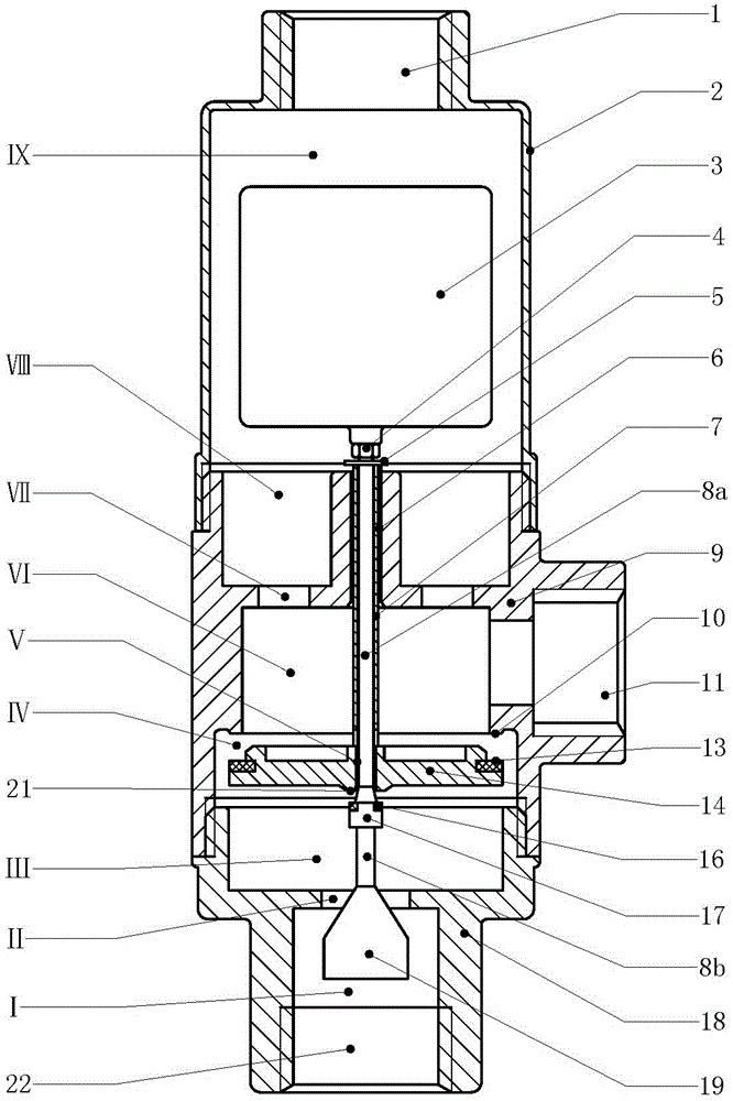
[0015] Embodiment 2 Attached figure 2 In the shown embodiment, the second built-in float valve of the present invention is characterized in that the float valve is mainly composed of a valve body (9), a main valve plate (14), a pressure relief valve core (17), a float ball (3 ) and the valve housing (2), wherein the valve housing (2) is connected to the upper end of the valve body (9), and the inner space of the upper end of the valve housing (2) and the valve body (9) constitutes the water chamber (Ⅷ), the water chamber The upper space of (Ⅷ) is connected to the exhaust port (1), and the floating ball (3) is set in the water chamber (Ⅷ); the valve body (9) has an upper valve chamber (Ⅵ) and a lower valve chamber (Ⅲ) , the center slideway (6) and the sealing surface a (10), the upper valve chamber (Ⅵ) and the lower valve chamber (Ⅲ) form a cylindrical space, the upper valve chamber (Ⅵ) is above the lower valve chamber (Ⅲ), the upper valve chamber The section of chamber (Ⅵ) i...


PUM


Abstract

The invention discloses a built-in floating ball valve, and relates to floating ball valves. The built-in floating ball valve mainly comprises a valve body, a main valve board, a decompression valve core, a floating ball and a valve case. The valve body is provided with an upper valve cavity, a lower valve cavity, a center sliding channel and a sealing face a, the center sliding channel is located in the center of the top portion of the wall body of the upper valve cavity, a round through hole is formed in the main valve board, the round through hole of the main valve body forms a decompression channel, a connecting rod is connected to the center of the upper end of the decompression valve core, a water inlet port is formed in one end of the valve body and is communicated with the lower valve cavity, a water outlet port is formed in the other end of the valve body and is communicated with the upper valve cavity, the valve case is connected to the upper end of the valve body, the space between the valve case and the upper end of the valve body forms a water chamber, the floating ball is arranged in the water chamber, and an exhaust port is formed in the top portion of the valve case. According to the built-in floating ball valve, the close direction of the valve board is the same as the flowing direction or water pressure direction of tap water, the valve board can be closed tightly by means of the pressure of the tap water, and the defect that an ordinary floating ball can not be closed tightly is overcome.

Description

technical field [0001] The invention relates to an automatic liquid level control device, in particular to a ball float valve. Background technique [0002] In life and production, people need water storage equipment, including thermal insulation water tanks for solar water heaters, water tanks for central heating systems, water towers for industrial and mining enterprises, fire pools, and boiler water supply tanks. In these equipment, the application of float valves for water supply can be used Save labor and prevent water waste. The existing float valve is to separate the valve from the float, and the valve is controlled by the crank arm and the float outside the valve, which has the disadvantages of inconvenient installation and use, easy failure, short service life, etc. If the valve is closed according to the direction of water flow or water pressure of tap water, the direction of pressure of tap water is the same as the direction of opening of the valve plate or valve...

Claims


Application Information

Patent Timeline
Patent Type & Authority Patents(China)
IPC IPC(8): F16K31/18F16K31/24
Inventor 周昀煜
Owner YANGZHOU DAYANG WATER SUPPLY EQUIP
Features
  • R&D
  • Intellectual Property
  • Life Sciences
  • Materials
  • Tech Scout
  • Unparalleled Data Quality
  • Higher Quality Content
  • 60% Fewer Hallucinations
Learn More