Orbit tool changer based on grooved wheel mechanism

A technology of a sheave mechanism and a changer, which is applied in the direction of tools, manufacturing tools, manipulators, etc., can solve the problems of a track tool changer such as large mass, affecting the reliability of space operation, and complex structure, and achieves compact structure, high reliability, The effect of large pose tolerance

Active Publication Date: 2013-10-23
HARBIN INST OF TECH
View PDF6 Cites 6 Cited by
  • Summary
  • Abstract
  • Description
  • Claims
  • Application Information

AI Technical Summary

Problems solved by technology

[0006] In order to solve the problem that the existing track tool changer has a large mass and an overly complicated structure, which affects the reliability of space operations, the present invention further provides a track tool changer based on a sheave mechanism

Method used


Image

  • Orbit tool changer based on grooved wheel mechanism
  • Orbit tool changer based on grooved wheel mechanism
  • Orbit tool changer based on grooved wheel mechanism

Examples


specific Embodiment approach 1

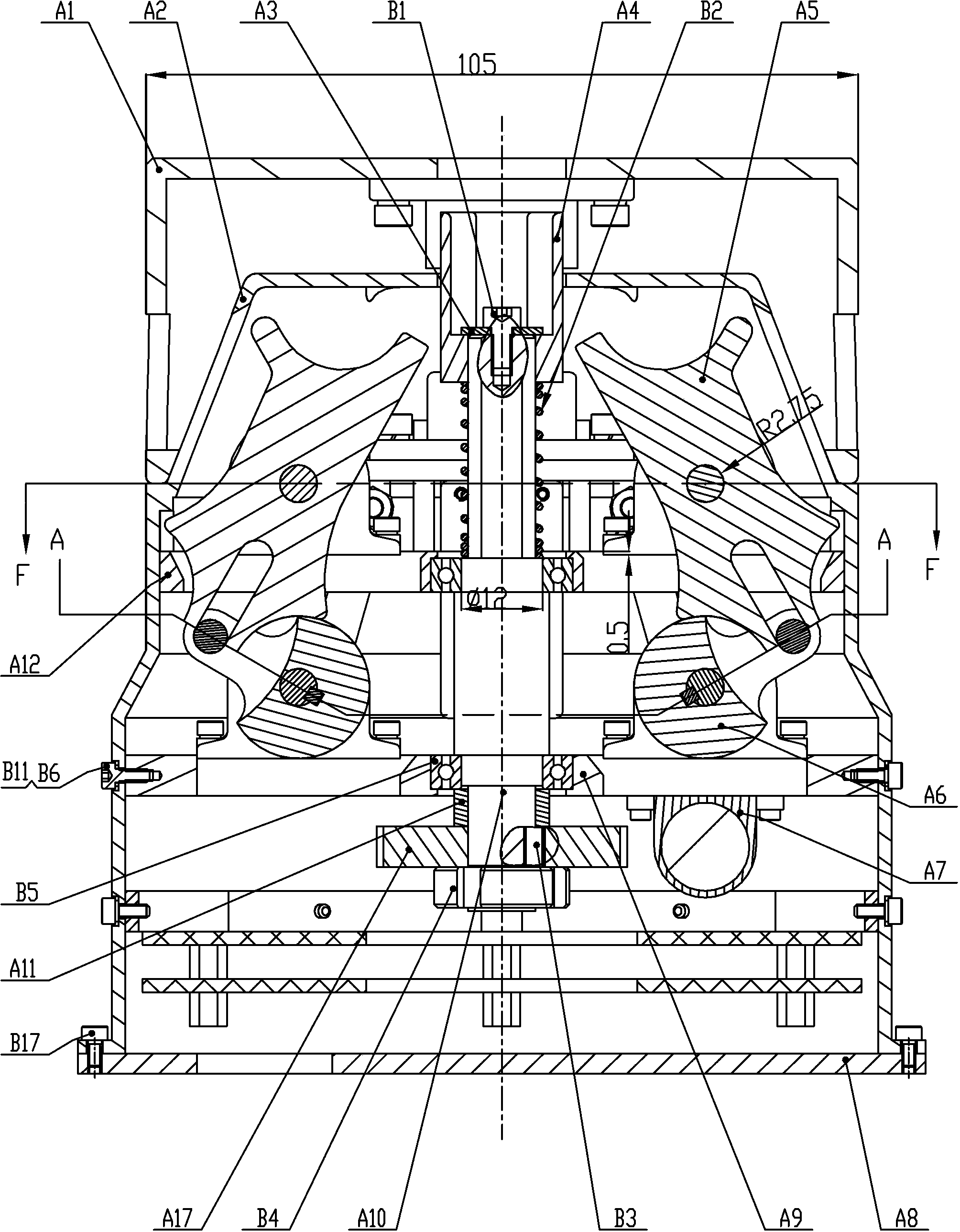
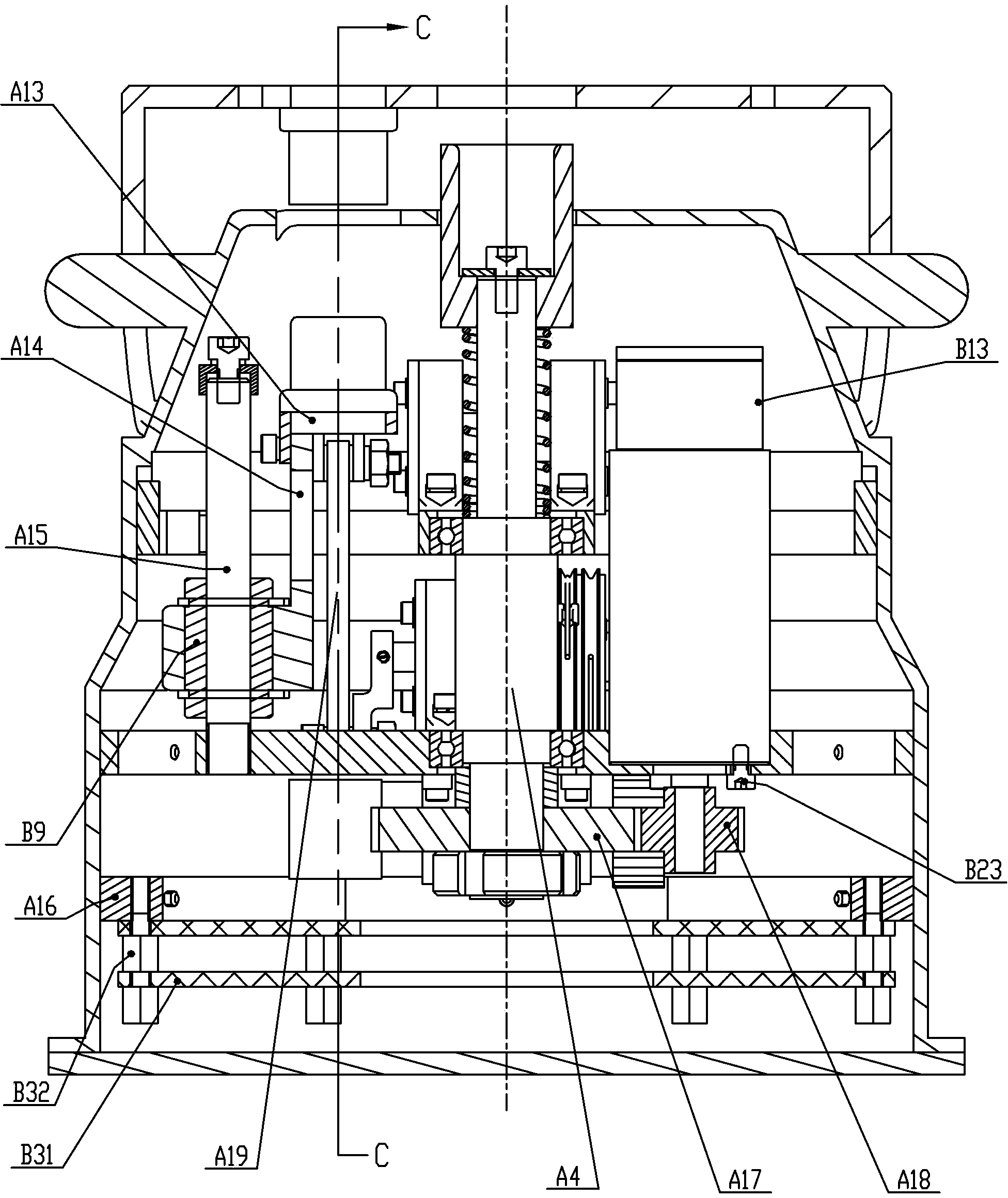
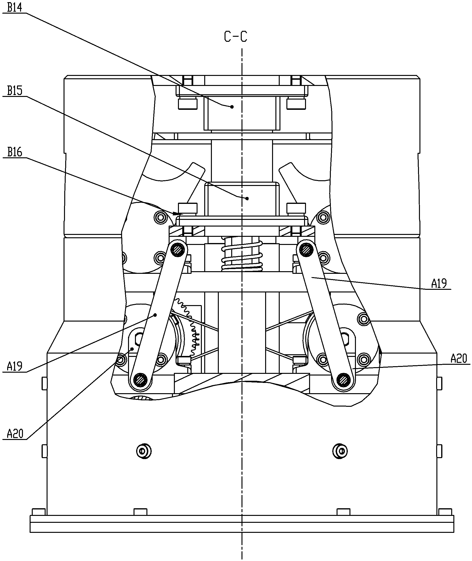
[0024] Specific implementation mode one: as Figures 1 to 8 As shown, the track tool changer based on the sheave mechanism of this embodiment includes a tool end interface A1, a housing A2, a bottom end cover A8, a lower support ring A9, an upper support ring A12, a circuit board support frame A16, and an electrical system 1. The first drive system and the second drive system, the upper support ring A12, the lower support ring A9, and the circuit board support frame A16 are installed in the housing A2 from top to bottom, the electrical system, the first drive system and the second drive system The two sets of driving systems are placed in the housing A2, the electrical system is placed on the circuit board support frame A16, the lower end surface of the housing A2 is connected to the bottom end cover A8; the tool end interface A1 is set on the housing A2;

[0025] The first set of drive system (to realize mechanical transmission) includes a first input device, a first transmis...

specific Embodiment approach 2

[0029] Specific implementation mode two: as Figures 1 to 8 As shown, the dial A6 in this embodiment is in the shape of a cam, and the dial pin A27 installed on the dial A6 moves linearly in the groove opened by the driven sheave A5. When the tool end interface is A1, the dial pin A27 breaks away from the linear groove of the sheave A5, so that the dial A6 can rotate idly, so as to realize the docking of the electrical connector interface. Other components and connections are the same as those in the first embodiment.

specific Embodiment approach 3

[0030] Specific implementation mode three: as Figures 1 to 8 As shown, the limit switch of the second set of drive system in this embodiment adopts a Hall sensor, and the Hall sensor B29 is glued to the support block A23 above the bearing seat, and the magnetic steel is embedded in the long axis gear of the dial On A22, the second drive system uses potentiometer B33 for absolute position sensing. Other compositions and connections are the same as those in Embodiments 1 and 2.


PUM


Abstract

An orbit tool changer based on a grooved wheel mechanism relates to the field of in-orbit service of space robots and aims to solve the problem that the conventional orbit tool changer has a large mass and a too complex structure, so that the reliability in space operation is affected. According to the orbit tool changer, two connection ways are achieved through two sets of driving systems. As for mechanical transmission, the motor of the first set of driving system is utilized to drive gears, the gears drive a transmission shaft, and a bolt sleeve on the transmission shaft is butted with a bolt head at another end so as to serve the function. As for electric transmission, before electric connector butting, grooved wheels are driven by driver plates to realize tool end locking, that is, the second set of driving system adopts a motor to input power and adjusts time series through the grooved wheels so as to realize output of the two actions of tool end locking and electric connector butting. The orbit tool changer has higher pose tolerance capability, a compact structure, high pose tolerance and high reliability and meets the requirement of in-orbit autonomous change of end tools of the space robots.

Description

technical field [0001] The invention relates to the field of on-orbit service of space robots, in particular to an orbital tool changer based on a sheave mechanism. Background technique [0002] With the advancement of technology, human activities are constantly expanding into space. According to statistics, an average of 80 to 130 satellites are launched each year in the world, but 2 to 3 satellites fail to be put into orbit correctly, and 5 to 10 of the satellites that are put into orbit correctly fail at the beginning of their life, which leads to huge economic loss. In order to recover losses as much as possible, various countries are researching space robot on-orbit service technology for the purpose of satellite maintenance, life extension and space junk removal by means of space robots. [0003] However, the complexity of space operations determines that a single end tool cannot complete all on-orbit tasks. Therefore, it is necessary to develop a multi-tool system t...

Claims


Application Information

Patent Timeline
Patent Type & Authority Applications(China)
IPC IPC(8): B25J19/00B64G4/00
Inventor 刘宇蒋再男刘宏韩峰
Owner HARBIN INST OF TECH
Why Eureka
Try Eureka