Electric fan

An electric fan and fan blade technology, applied in the field of electric fans, can solve the problems of inability to form a rotating airflow, limited wind angle, uncomfortable wind force, etc.

Inactive Publication Date: 2013-10-23
深圳市巨迪能源科技有限公司
View PDF6 Cites 3 Cited by
  • Summary
  • Abstract
  • Description
  • Claims
  • Application Information

AI Technical Summary

Problems solved by technology

[0002] Existing electric fans use airflow to enter from the back, blow out from the front, and change the wind direction by shaking the head. The angle of the blown wind is very limited, and it cannot form a rotating airflow when used in an indoor space. The straight blowing wind is very uncomfortable. comfortable

Method used


Image

  • Electric fan
  • Electric fan
  • Electric fan

Examples


specific Embodiment approach 1

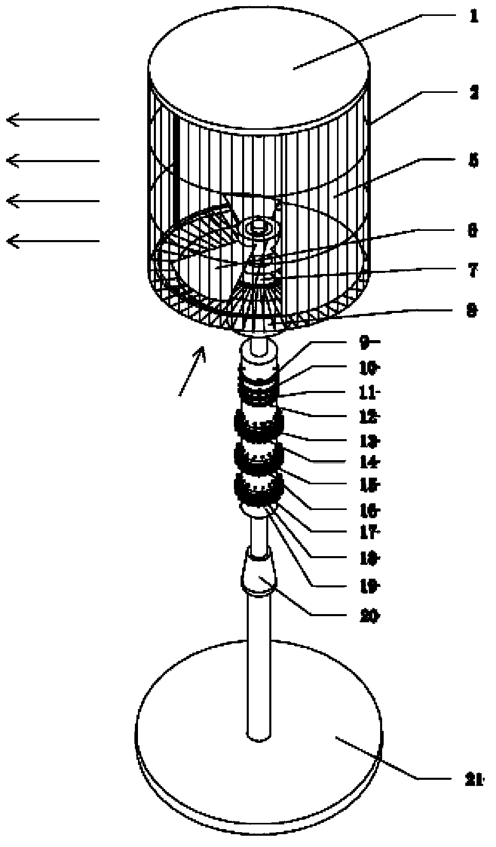
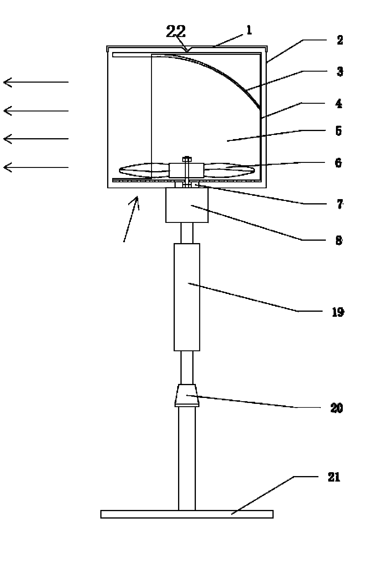
[0024] Such as Figure 1 to Figure 3 As shown in the figure, the arrow in the lower left corner of the motor indicates the direction of airflow entering from below, and the arrow on the left indicates the 360-degree output wind.

[0025] An electric fan comprising a base, a vertical pole, a fan blade, a motor, and an electric control device. The vertical pole is arranged on the base, the motor is connected with the fan blade, and the motor and the fan blade are arranged on the vertical pole The electric control device controls the motor, and also includes a rotating deflector, the blades of the wind blade are set to blow upward, the deflector covers the wind blade from the upper part of the wind blade, and the top of the deflector is provided with a seal The bottom of the deflector is provided with a sealing cover, and the side of the deflector is provided with at least two air outlets. Preferably, three air outlets in the vertical direction are evenly arranged on the side of th...

specific Embodiment approach 2

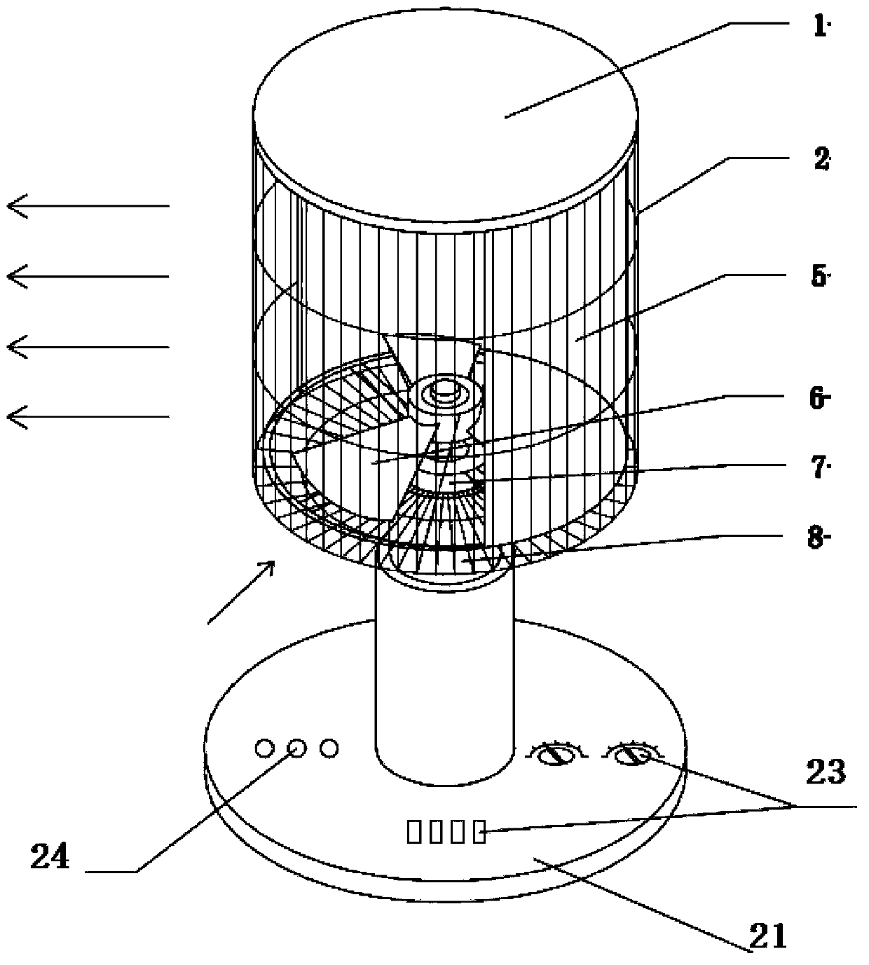
[0029] Such as Figure 4 As shown in the figure, the arrow in the upper left corner indicates the direction of airflow entering from above, and the arrow on the left indicates the 360-degree output wind.

[0030] An electric fan comprising a base, a vertical pole, a fan blade, a motor, and an electric control device. The vertical pole is arranged on the base, the motor is connected with the fan blade, and the motor and the fan blade are arranged on the vertical pole The electric control device controls the motor, and also includes a rotating deflector, the blades of the wind blade are set to blow downward, the deflector covers the wind blade from the lower part of the wind blade, and the bottom of the deflector is provided At least two air outlets are provided on the side of the sealing cover and the deflector. Preferably, three air outlets in the vertical direction are evenly arranged on the side of the deflector. The airflow enters from above and blows out 360 degrees around. ...


PUM


Abstract

The invention provides an electric fan, which mainly consists of a base, an upright tube, a lifting regulation and electric control device, an annular knob switch, an annular halo indicator light, an electromotor, a fan blade, a transmission used for a rotary air director, the rotary air director and a safety shield, wherein the annular knob switch can rotate within 360 degrees left and right. The electric fan disclosed by the invention adopts a mode that the fan blade upwards or downwards blows, airflow enters from bottom or top by the air director and rotation and is blown out in a rotating mode at an angle of 360 degrees to the periphery to form rotary airflow, blown air enables people to feel comfortable, rotary airflow can be formed in indoor space without shaking the head, the periphery of the fan can be blown so as to achieve a purpose of further blowing at an angle of 360 degrees, the electric fan can be arranged at will without distinguishing front and back, and the watching focuses at the angle of 360 degrees at the periphery are the same.

Description

Technical field [0001] The invention relates to a blowing device, in particular to an electric fan. Background technique [0002] Existing electric fans use airflow to enter from the back and blow out from the front. The wind direction is changed by shaking the head. The angle of the wind is very limited, and the rotating airflow cannot be formed in the indoor space. The direct wind is very unpleasant. Comfortable. Summary of the invention [0003] In order to solve the problems in the prior art, the present invention provides an electric fan. [0004] An electric fan comprising a base, a vertical pole, a fan blade, a motor, and an electric control device. The vertical pole is arranged on the base, the motor is connected with the fan blade, and the motor and the fan blade are arranged on the vertical pole , The electric control device controls the motor, and further includes a rotating deflector. The blades of the wind blade are set to blow upward or downward. The deflector covers...

Claims


Application Information

Patent Timeline
Patent Type & Authority Applications(China)
IPC IPC(8): F04D25/08F04D29/44
Inventor 游海雄
Owner 深圳市巨迪能源科技有限公司
Why Eureka
Try Eureka