Variable-angle range finder and use method thereof

A rangefinder and angle-changing technology, applied in the field of measuring devices, can solve the problems of affecting the measured value, large reflection, excessive temperature difference, etc., and achieve the effect of flexible layout, simple operation method and broad application prospects

Active Publication Date: 2020-12-25
STATE GRID FUJIAN ELECTRIC POWER CO LTD +1
View PDF19 Cites 0 Cited by
  • Summary
  • Abstract
  • Description
  • Claims
  • Application Information

AI Technical Summary

Problems solved by technology

However, due to large fluctuations in the water level of the water collection well, rapid changes in temperature and humidity in the well, and poor water quality, the contact measuring element is prone to fouling and the signal transmission distance is long. The amount of maintenance is reduced, and serious safety risks are caused
[0005](2) If all the measurement work in daily operation and maintenance is measured with high-precision professional instruments, the company's operating costs will be greatly increased
When the working environment is not ideal, such as strong sunlight, excessive temperature difference, or large reflection on the surface of the measured object, it will seriously affect the final measurement value
[0007](4) The method of visual reading of the water gauge requires manpower. When the water gauge is blocked by silt or debris, the reading error is large and the real-time performance is not high , the safety of people who read the water level in harsh environments cannot be guaranteed

Method used


Image

  • Variable-angle range finder and use method thereof
  • Variable-angle range finder and use method thereof
  • Variable-angle range finder and use method thereof

Examples


Embodiment 1

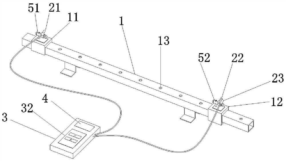
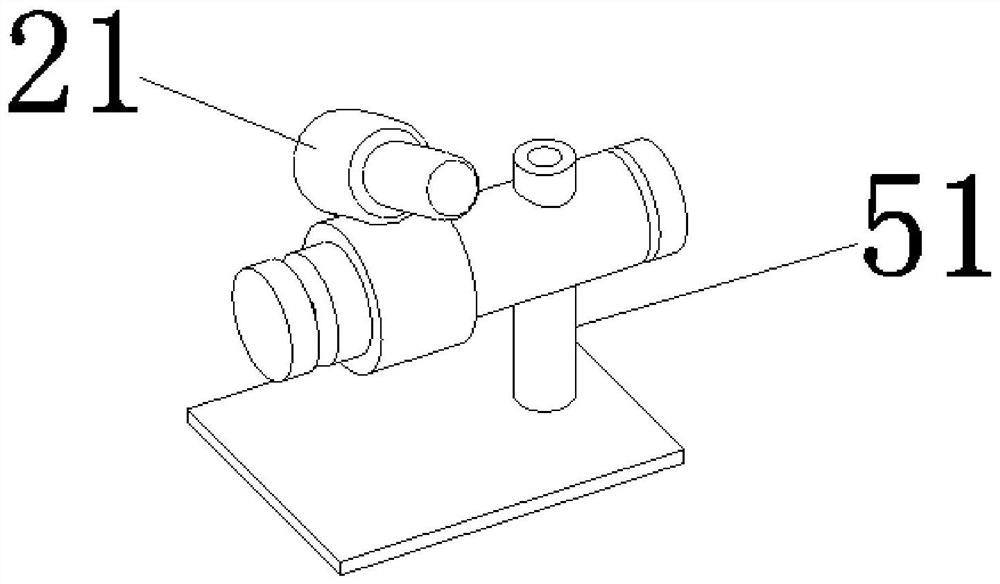
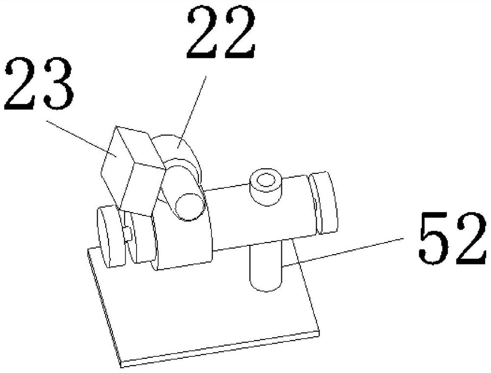
[0039] see Figure 1 to Figure 4 , a variable angle range finder, comprising a measuring pole 1, a first laser emitter 21, a second laser emitter 22, a biaxial inclination sensor 23, a controller 3 and a display device 4; the measuring pole 1 One end of the fixed sleeve is provided with a fixed block 11, and the first laser emitter 21 is rotationally connected with the fixed block 11 through a first rotating mechanism 51; The second laser emitter 22 is rotationally connected with the slider 12 through the second rotating mechanism 52, and the biaxial inclination sensor 23 is fixedly connected with the second laser emitter 22; the first laser emitter 21 is used For locating the target position, the second laser transmitter 22 is used for locating and measuring the angle between different positions on the shaft of the pole 1 to the target position, and the biaxial inclination sensor 23 is used for obtaining electrical signals corresponding to the angle; The input end of the con...

Embodiment 2

[0044] A method for using a variable-angle range finder, comprising the following steps:

[0045] Place the measuring pole 1 at the measuring point, turn on the first laser emitter 21, adjust the first rotating mechanism 51 so that the light spot of the first emitter is aligned with the target position;

[0046]Move the slider 12, fix the slider 12 at the initial measurement point, adjust the second rotating mechanism 52 so that the light spot of the second emitter is aligned with the light spot of the first emitter, and at the same time control the single-chip microcomputer through the keyboard to obtain the current dual-axis inclination sensor 23 to obtain The electrical signal of the angle of the angle is used as the initial angle; move the slider 12 to the A measurement point in one direction of the initial measurement point, adjust the second rotating mechanism 52 so that the light spot of the second emitter is aligned with the light spot of the first emitter, and obtain A...


PUM


Abstract

The invention relates to a variable-angle range finder. The variable-angle range finder comprises a measuring support rod, a first laser emitter, a second laser emitter, a double-axis tilt angle sensor, a controller and a display device, wherein a fixed block fixedly sleeves one end of the measuring support rod, and the first laser emitter is rotatably connected with the fixed block through a first rotating mechanism; a sliding block slidably sleeves a rod body of the measuring support rod, the second laser emitter is rotatably connected with the sliding block through a second rotating mechanism, and the double-axis tilt angle sensor is fixedly connected with the second laser emitter; an input end of the controller is electrically connected with the double-axis tilt angle sensor and is used for receiving an electric signal of an angle acquired by the double-axis tilt angle sensor; and the display device is electrically connected with an output end of the controller.

Description

technical field [0001] The invention relates to a range finder with variable angle, which belongs to the technical field of measuring devices. Background technique [0002] In the production and operation of hydropower, it is often necessary to carry out various measurement tasks, such as judging the water level of the collection well, determining the safety distance, measuring the size of the equipment, the height of the building, etc. Although this type of work does not require high-precision measurement, it often has the characteristics of wide distribution of work locations, complex structure of the equipment under test, and harsh measurement conditions. It is also impossible to ask professional observers to measure on the spot. [0003] There are mainly four types of existing measurement methods in hydropower plants. One is to use installed liquid level sensors, such as water level, oil level measurement, etc.; the other is to use professional instruments to measure by...

Claims


Application Information

Patent Timeline
IPC IPC(8): G01C3/02
CPCG01C3/02
Inventor 郑荫钦杨玮光陈罗方国成董良彬
Owner STATE GRID FUJIAN ELECTRIC POWER CO LTD
Why Eureka
Try Eureka