Anti-falling pair roller

A technology for rollers and rollers, used in elevators, elevators in buildings, transportation and packaging, etc., can solve the problem of not changing the dominance of wire rope traction elevators, and achieve flexible and changeable shapes, simple overall structure, and long-term performance. The effect of distance carrying

Inactive Publication Date: 2006-01-04
周友仁
View PDF0 Cites 15 Cited by
  • Summary
  • Abstract
  • Description
  • Claims
  • Application Information

AI Technical Summary

Problems solved by technology

Although hydraulic elevators, rack and pinion elevators have been put into use, and linear motor elevators are under development, they still cannot change the dominant position of wire rope traction elevators.

Method used


Image

  • Anti-falling pair roller
  • Anti-falling pair roller
  • Anti-falling pair roller

Examples


Embodiment Construction

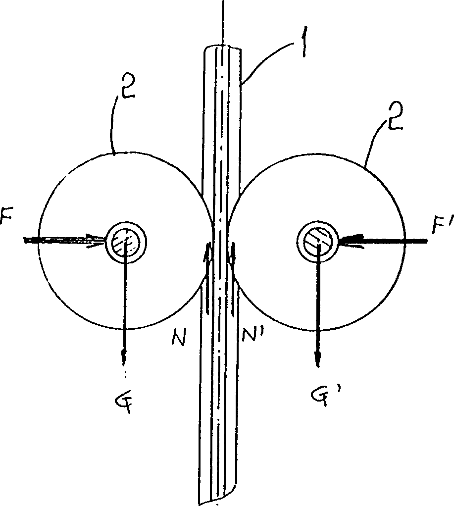
[0032] Such as figure 1 Shown, the present invention provides a kind of anti-falling roller that can rise, descend or stop along rail 1 (or other supports), and its basic structure is to go out a pair of distribution on rail (or other supports, such as I-beam, Two rollers 2 with equal value and opposite acting force are applied on both sides of column, utility pole, suspension tape, etc.). These two rollers 2 are usually symmetrical and opposite, and are called twin wheels (Twin Wheels). The applied equal and opposite action force is essentially the action force and reaction force described by Newton's third law. This group of action force and reaction force is transmitted to the surface of rail 1 (or other supports) through two rollers 2 to generate positive pressure, thereby generating static friction in the tangential direction of the surface of rail 1 (or other supports) (in the figure N, N'). If the direction of the force (F, F' in the figure) applied to the two rolle...


PUM


Abstract

The falling preventing paired roller apparatus includes track, and two rollers in the basically same structure and set on two sides of the track. Of the two rollers, at least one is active roller with axle controlled by a drive mechanism and a normally closed brake. The rollers on the two sides of the track contact the track to form a basically symmetric arrangement. One force applying unit makes the two rollers generate equal and opposite pressures on the track to overcome gravitational force. The present invention has the advantages of simple structure and wide use, and may be used widely in vertical or inclined transportation machines.

Description

technical field [0001] The invention relates to a roller device, in particular to a pair of anti-drop rollers that can be applied to the bearing and driving device of vertical lifting or slope vehicles. Background technique [0002] Existing vehicles generally cannot travel on slopes exceeding 30°. Because as the slope increases, the positive pressure of the wheels on the slope decreases and the friction between the wheel and the road surface decreases, and the vehicle will definitely fall due to gravity. Therefore, suspension wire ropes are widely used in vertical lifting machinery (such as elevators, cages) and slope carrying machinery (such as cable cars, cranes) in order to overcome the falling effect of gravity. This method is very mature, but because the steel wire rope can only bear tension, it can only be applied on a straight track; and the self-weight and winding device of the steel wire rope have certain limitations on the application of high-speed and high-lift ...

Claims


Application Information

Patent Timeline
Patent Type & Authority Applications(China)
IPC IPC(8): B66B11/04B66B5/18
Inventor 周友仁
Owner 周友仁
Why Eureka
Try Eureka