Thermal resistance testing method and thermal resistance testing device

A test method and technology of a test device, applied in the field of testing, can solve the problems of inaccurate testing, failure to consider the heat dissipation problem of triodes and heat sinks, and achieve the effect of improving test accuracy.

Inactive Publication Date: 2013-10-23
ZTE CORP +1
View PDF4 Cites 23 Cited by
  • Summary
  • Abstract
  • Description
  • Claims
  • Application Information

AI Technical Summary

Problems solved by technology

The defect of this method is that it does not consider the heat dissipation of the triode in the environment and the heat dissipation of the radiator itself, resulting in the heat being concentrated on the radiator and causing the test to be inaccurate

Method used


Image

  • Thermal resistance testing method and thermal resistance testing device
  • Thermal resistance testing method and thermal resistance testing device
  • Thermal resistance testing method and thermal resistance testing device

Examples


Embodiment approach

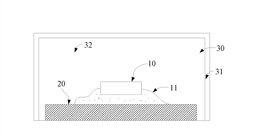
[0040] Under the preferred embodiment, as figure 2 As shown, the heat insulation component 30 includes a heat insulation shell 31 with a unidirectional opening, and the opening of the heat insulation shell 31 is used to form a unidirectional heat conduction channel 100 for conducting heat generated by the heating component 10 in one direction.

[0041]Preferably, the heat insulation component 30 also includes a heat insulation filling material 32 filled in the gap between the heat insulation shell 31 and the composite heat conducting material 20, continue to refer to figure 2 , the heat insulating filling material 32 is used to further prevent the heat generated by the heating component 10 from being lost to the external environment. In actual application, when there is still a gap between the opening of the heat insulation shell 31 and the heat insulation filling material 32, it should also be understood that the gap is filled with the heat insulation filling material 32 to...


PUM


Abstract

The invention discloses a thermal resistance testing method and a thermal resistance testing device. The method comprises the following steps that: a thermal insulation part is arranged at one side of a first test surface of a to-be-tested piece; a heating part which is fixed above the to-be-tested piece is arranged between the thermal insulation part and the to-be-tested piece; a radiating part is arranged at one side of a second test surface of the to-be-tested piece; in the thermal resistance testing process, heat generated by the heating part passes through the to-be-tested piece and then is transferred to the radiating part by a one-way heat conduction channel formed by the thermal insulation part; the temperature values of the first test surface and the second test surface of the to-be-tested piece are tested respectively; the absolute temperature difference value DeltaT is calculated; the power dissipation value P of the heating part is obtained; the thermal resistance value R of the to-be-tested piece can be obtained according to a mathematic expression, namely R is equal to DeltaT/P. According to the thermal resistance testing method and the thermal resistance testing device, as the thermal insulation part which can be used for leading all the heat generated by the heating part to a tested composite heat conduction material, the problem that the thermal resistance testing is not accurate as the heat generated by the heating part is lost in the environment in the thermal resistance testing process can be solved.

Description

technical field [0001] The present invention relates to the field of testing, in particular, to a method and device for testing thermal resistance of composite thermally conductive materials. In addition, the method and device for testing thermal resistance provided by the present invention can also be applied to other types of materials other than composite thermally conductive materials. on the test piece. Background technique [0002] At present, with the increase in the density of electronic components and the miniaturization of high-power electronic equipment, the thermal reliability of electronic products has been paid more and more attention. The thermal conductivity puts forward higher requirements. [0003] Generally, there are two parameters that represent the thermal conductivity of a material: thermal conductivity and thermal resistance. Among them, thermal conductivity is used to represent the thermal conductivity of a certain material, and thermal resistance i...

Claims


Application Information

Patent Timeline
Patent Type & Authority Applications(China)
IPC IPC(8): G01N25/20
Inventor 赵丽何为刘哲王玉付红志
Owner ZTE CORP
Why Eureka
Try Eureka