Radar target detecting system based on matrix filling and detecting method thereof
What is AI technical title?
AI technical title is built by PatSnap AI team. It summarizes the technical point description of the patent document.
A matrix filling, radar target technology, applied in radio wave measurement systems, instruments, etc., can solve problems such as increasing system cost, and achieve the effect of reducing sampling rate, reducing system cost, and overcoming dependence.
Active Publication Date: 2015-04-22
XIDIAN UNIV
View PDF4 Cites 0 Cited by
Summary
Abstract
Description
Claims
Application Information
AI Technical Summary
This helps you quickly interpret patents by identifying the three key elements:
Problems solved by technology
Method used
Benefits of technology
Problems solved by technology
Among them, the random demodulator needs to generate a high-speed pseudo-random sequence, and the change rate of the sequence must at least meet the Nyquist rate, and to generate a high-speed pseudo-random sequence that meets the Nyquist rate, the system cost must be increased
Method used
Image
Click on the blue label to locate the original text in one second.
Reading with bidirectional positioning of images and text.
Examples
Embodiment 1
[0057] refer to Image 6 , the implementation steps of this example are as follows:
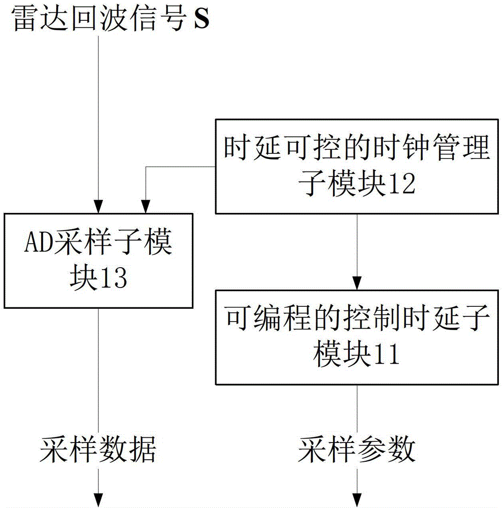
[0058] Step 1, take the moment when each pulse echo starts to be received as the reference time point, and take the reference time point as the initial time T with a probability of 1 / 2 0 , denoted as T 0 =0.
[0059] Step 2, after the initial moment, generate a random phase ΔT according to the interval length L k , according to the random phase ΔT k produces a frequency of f s / N sampling clock.
[0060] Step 3: The sampling module performs down-sampling on the radar echo signal S according to the generated sampling clock to obtain sampling data.
[0061] Step 4, the above sampling data and random phase ΔT k , stored through the data storage waveform reconstruction module.
[0062] Step 5, the data storage waveform reconstruction module according to the stored sampling data and random phase ΔT k , obtain the reconstructed radar echo signal X through the matrix filling algorithm:
[...
Embodiment 2
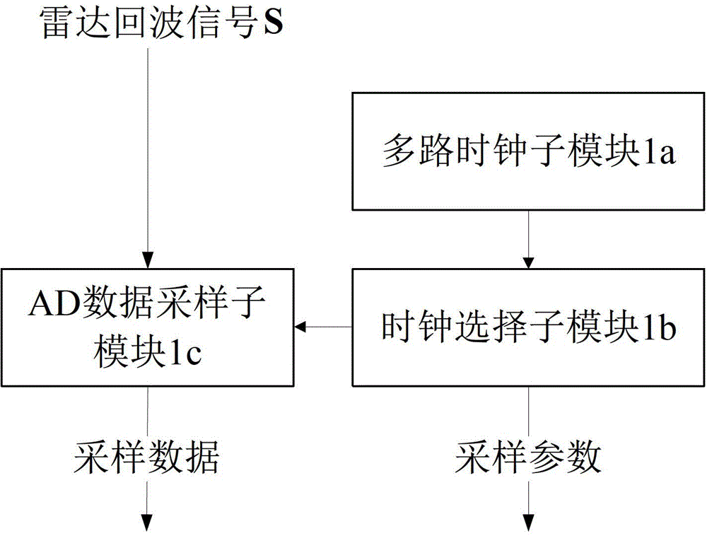
[0072] refer to Figure 7 , the implementation steps of this example are as follows:
[0073] Step 1: Take the time when each pulse echo starts to be received as the reference time point, and use the probability of 1 / 2 to set the reference time point after L / 2 time as the initial time T' 0 , denoted as T' 0 =L / 2,L=mT s , m is a positive even number.
[0074] Step 2, generate N channels with frequency f s / N clocks, after the initial time, randomly select the p-th clock among the N clocks according to the interval length L.
[0075] Step 3: The sampling module performs down-sampling on the radar echo signal S according to the selected p-th clock to obtain sampling data.
[0076] Step 4: Store the sampled data and the selected clock path p through the data storage waveform reconstruction module.
[0077] Step 5, the data storage waveform reconstruction module obtains the reconstructed radar echo signal X' through the matrix filling algorithm according to the sampled data a...
PUM
Abstract
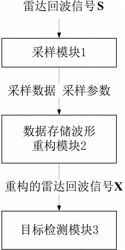
The invention relates to a radar target detecting system based on matrix filling and a detecting method of the radar target detecting system. The radar target detecting system mainly solves the problems that, in the prior art, cost is high, the data storage quantity is large, and the system implementation mode is limited. The radar target detecting system comprises a sampling module (1), a data storage waveform reconstitution module (2) and a target detecting module (3). The sampling module (1) conducts rate reduction sampling on a radar echo signal S and transmits sampling data and sampling parameters to the data storage waveform reconstitution module (2). The data storage waveform reconstitution module (2) obtains a reconstituted radar echo signal X through the matrix filling algorithm according to the sampling data and the sampling parameters and transmits the reconstituted radar echo signal X to the target detecting module (3). The target detecting module (3) conducts pulse compression on the reconstituted radar echo signal X, and then conducts dynamic target detection and constant false alarm detection on the pulse compression result XMF through the target detecting module (3). The radar target detecting system reduces the system cost, shrinks the data storage space, improves the system implementation flexibility and can be used for radar target detecting.
Description
technical field [0001] The invention belongs to the technical field of radar signal processing, and further relates to a radar signal down-sampling reconstruction system, which can be used for target detection. Background technique [0002] Under the requirements of high precision and high resolution, modern radar signal processing greatly increases the amount of sampled data, which poses a severe challenge to data storage and transmission. The existing radar signal down-sampling system mainly includes low-speed parallel multi-channel down-sampling system, down-sampling system of analog information converter based on compressed sensing, etc. in: [0003] The low-speed parallel multi-channel AD down-sampling system mainly uses multiple channels for parallel sampling, the number of channels is equal to the down-sampling rate, and the sampling clock phase of each channel is different from the Nyquist sampling time interval. The system obtains all the data through multi-channe...
Claims
Application Information
Patent Timeline
Application Date:The date an application was filed.
Publication Date:The date a patent or application was officially published.
First Publication Date:The earliest publication date of a patent with the same application number.
Issue Date:Publication date of the patent grant document.
PCT Entry Date:The Entry date of PCT National Phase.
Estimated Expiry Date:The statutory expiry date of a patent right according to the Patent Law, and it is the longest term of protection that the patent right can achieve without the termination of the patent right due to other reasons(Term extension factor has been taken into account ).
Invalid Date:Actual expiry date is based on effective date or publication date of legal transaction data of invalid patent.

