
Disconnecting switch and conducting loop structure thereof

A technology of conductive loops and isolating switches, which is applied in the direction of circuits, electric switches, and switches with unconnected bridge contacts, etc., can solve problems that affect the safe and stable operation of equipment and power grids, and low closing success rate, so as to avoid safe and stable operation , simple structure, and the effect of improving the success rate of operation

Active Publication Date: 2013-10-23
STATE GRID CORP OF CHINA +2
View PDF6 Cites 5 Cited by
  • Summary
  • Abstract
  • Description
  • Claims
  • Application Information

AI Technical Summary

Problems solved by technology

[0005] In view of this, the first object of the present invention is to provide a conductive loop structure. The structural design of the conductive loop structure can effectively solve the problem of low closing success rate, which further affects the safe and stable operation of equipment and power grids. The present invention The second object of is to provide an isolating switch including the above conductive loop structure

Method used


Image

  • Disconnecting switch and conducting loop structure thereof
  • Disconnecting switch and conducting loop structure thereof
  • Disconnecting switch and conducting loop structure thereof

Examples


Embodiment Construction

[0033] The first object of the present invention is to provide a conductive loop structure. The structural design of the conductive loop structure can effectively solve the problem of low closing success rate, which further affects the safe and stable operation of equipment and power grids. The second object of the present invention The object is to provide an isolating switch including the above conductive loop structure.

[0034] The following will clearly and completely describe the technical solutions in the embodiments of the present invention with reference to the accompanying drawings in the embodiments of the present invention. Obviously, the described embodiments are only some, not all, embodiments of the present invention. Based on the embodiments of the present invention, all other embodiments obtained by persons of ordinary skill in the art without making creative efforts belong to the protection scope of the present invention.

[0035] see Figure 4-Figure 7 , Th...


PUM


Abstract

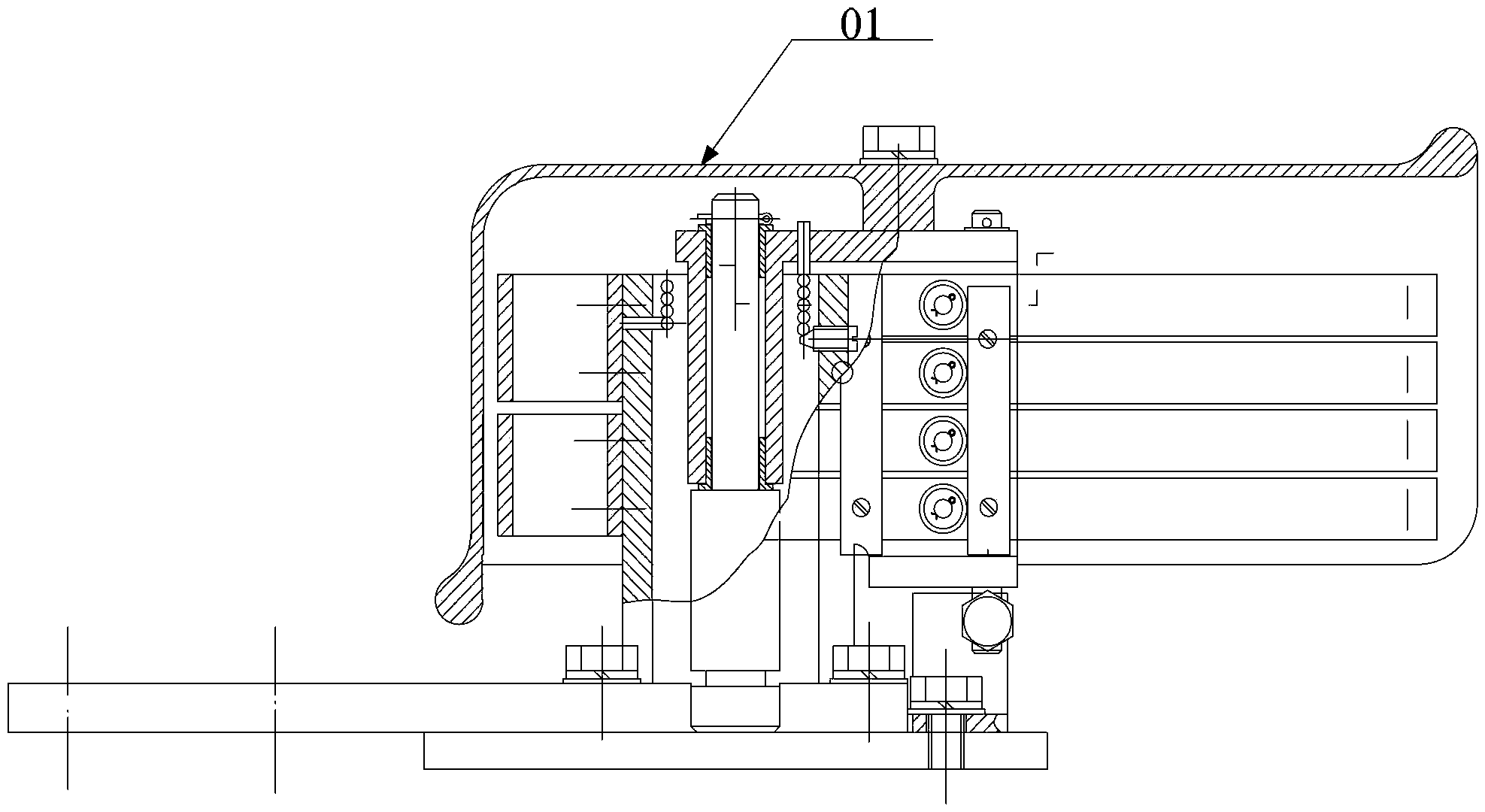
The invention discloses a conducting loop structure. The conducting loop structure is characterized in that the sidewall of one side of a fixed contact, close to a rotating arm, comprises a first wall and a second wall which are distributed up and down; one end of the first wall is fixedly connected with the upper wall of the fixed contact while the other end of the first wall extends into the fixed contact; a first compressing spring is arranged between the other end of the first wall and the upper wall, and two ends of the first compressing spring are respectively connected with the upper wall and the first wall; one end of the second wall is fixedly connected with the lower wall of the fixed contact while the other end of the second wall extends into the fixed contact; a second compressing spring is arranged between the other end of the second wall and the upper wall, and two ends of the second compressing spring are respectively connected with the lower wall and the second wall; a clamping groove used for containing a moving contract is formed between the first wall and the second wall; and the moving contract is specifically a conducting plate which can be arranged into the clamping groove in a clamping manner. By adopting the conducting loop structure, the problem that the low switching-in success rate is generated to further impact the safety and stability of equipment and a power grid in running can be solved. The invention also provides a disconnecting switch comprising the conducting loop structure.

Description

technical field [0001] The invention relates to the technical field of high-voltage switches, more specifically, to an isolating switch and its conductive circuit structure. Background technique [0002] Three-column horizontal rotary double-break high-voltage AC isolating switch is widely used in 220kV outdoor power distribution devices to realize electrical isolation. [0003] see Figure 1 to Figure 3 , The isolation switch includes three insulators 04 arranged side by side, the ones on both sides are supporting insulators, the middle one is a rotating insulator, the top of the supporting insulator is provided with a static contact 01, and the top of the rotating insulator is provided with a rotating insulator through a bracket 03. The center line of the rotating arm 02, and the two ends of the rotating arm 02 are provided with movable contacts 05. In the prior art, there are two closing methods, one of which is the contact turning-in type: when the static contact is in ...

Claims


Application Information

Patent Timeline
IPC IPC(8): H01H31/16H01H1/50
Inventor 金佳敏赵深林群梅照赛
Owner STATE GRID CORP OF CHINA
Learn More