Image forming system, image forming apparatus and external terminal

一种外部终端、图像的技术,应用在图像通信、电气元件等方向,能够解决通信业务量增大等问题,达到降低通信业务量的效果

Active Publication Date: 2013-10-23
KONICA MINOLTA BUSINESS TECH INC
View PDF4 Cites 2 Cited by
  • Summary
  • Abstract
  • Description
  • Claims
  • Application Information

AI Technical Summary

Problems solved by technology

[0007] However, in the remote operation technique described above, it is necessary to transmit the operation screen data itself from the image forming apparatus to the external terminal every time in response to the operation input (the capacity is relatively large), and there is a network between the image forming apparatus and the external terminal. The problem of increased communication traffic

Method used


Image

  • Image forming system, image forming apparatus and external terminal
  • Image forming system, image forming apparatus and external terminal
  • Image forming system, image forming apparatus and external terminal

Examples


no. 1 approach

[0043]

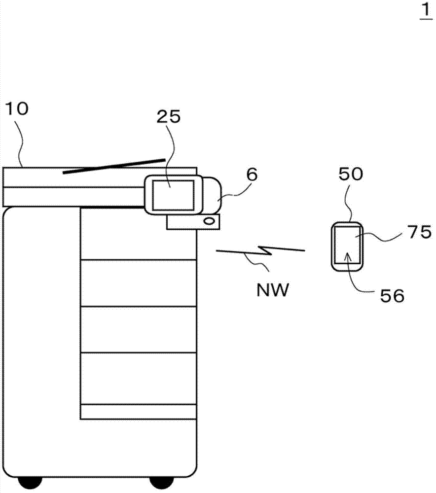
[0044] figure 1 is a diagram showing the image forming system 1 . Such as figure 1 As shown, the image forming system 1 includes an image forming device 10 and an external terminal device 50 .

[0045]The image forming device 10 and an external terminal device (also simply referred to as an external terminal) 50 are connected so as to be communicable with each other via a network NW. The network NW is composed of a LAN (Local Area Network), the Internet, and the like. For example, the image forming apparatus 10 and the external terminal 50 are wirelessly connected via a network NW (including wireless LAN and the like).

[0046] The external terminal 50 is a device capable of operating (remotely operating) the image forming apparatus 10 . A user in image forming system 1 can perform various operations on image forming apparatus 10 using external terminal 50 . In addition, the external terminal 50 is also called an operation device (or a remote operation device) ...

no. 2 approach

[0128] The second embodiment is a modified example of the first embodiment.

[0129] Hereinafter, the description will focus on differences from the first embodiment.

[0130] In the above embodiment, a case was exemplified in which image forming apparatus 10 determines whether or not program PM2 having the same function as program PM1 to which an execution instruction has been given via operation screen GS is installed in external terminal 50 .

[0131] On the other hand, in this second embodiment, a case where the external terminal 50 itself performs this determination is exemplified.

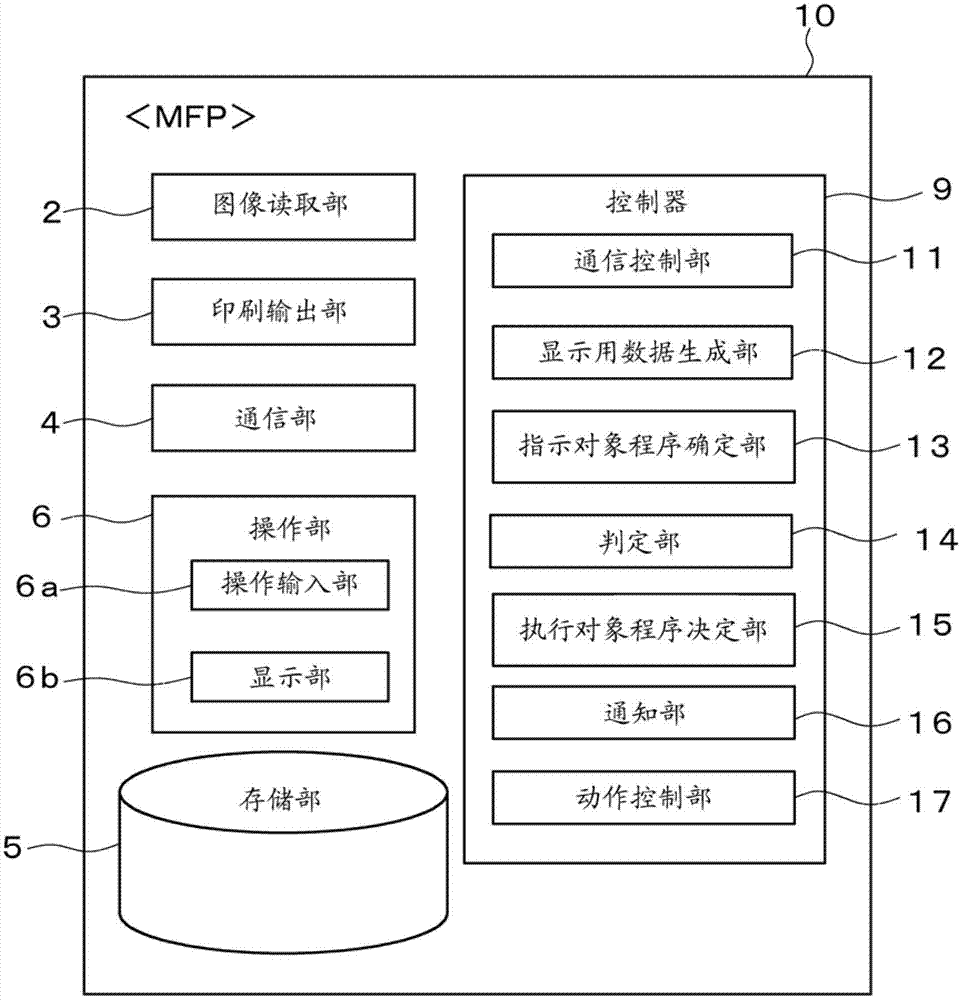
[0132] Figure 11 It is a diagram showing functional blocks of the image forming apparatus 10 according to the second embodiment.

[0133] Such as Figure 11 As shown, in this second embodiment, the controller 9 implements various processing units including the communication control unit 11 , the display data generation unit 12 , and the operation control unit 17 . In addition, each proce...


PUM


Abstract

An image forming system comprises an image forming apparatus and an external terminal. The image forming apparatus has a receiving part for receiving operation input information on an operation input into an operation screen from the external terminal, a specifying part for specifying a first program to which an execution instruction is given through the operation screen on the basis of the operation input information, a determination part for determining a second program having the same function as that of the first program as an execution object program on the condition that the second program is installed in the external terminal, and a notification part for notifying the external terminal that the second program is determined as the execution object program. The external terminal executes a processing in accordance with the second program and displays a result of the processing executed in accordance with the second program.

Description

technical field [0001] The present invention relates to an image forming system including an image forming apparatus such as an MFP (Multi-Functional Peripheral) and related technologies. Background technique [0002] There is a technology in which an image forming apparatus is operated by an external terminal. [0003] For example, Patent Document 1 discloses a technique of directly transmitting the operation screen data itself (bitmap image data, etc.) from the image forming apparatus to the external terminal to display the operation screen on the display unit of the external terminal, The operation position information (pressed position information, etc.) in the operation screen is transmitted and received, and the operation input in the operation screen is accepted. It is the so-called remote operation technology based on remote connection. [0004] [Prior Art Literature] [0005] 【Patent Literature】 [0006] [Patent Document 1] Japanese Patent Application Laid-Open ...

Claims


Application Information

Patent Timeline
Patent Type & Authority Applications(China)
IPC IPC(8): H04N1/00
CPCH04N2201/0074H04N1/00204H04N1/00408H04N2201/001H04N1/0049H04N2201/0094
Inventor 小林美奈子小卷由夫长谷淳一吉村智也田岛宏树涩田义明
Owner KONICA MINOLTA BUSINESS TECH INC
Why Eureka
Try Eureka