Moving part structure of linear sliding rail

A technology of linear slides and moving parts, applied in the direction of linear motion bearings, bearings, shafts and bearings, etc., can solve problems such as loosening, increase the rigidity of the joint, reduce the probability of failure, and improve the service life.

Active Publication Date: 2013-10-30
CHIEFTECH PRECISION
View PDF9 Cites 0 Cited by
  • Summary
  • Abstract
  • Description
  • Claims
  • Application Information

AI Technical Summary

Problems solved by technology

[0006] In actual use, it is found that the bending extension piece corresponding to the foot of the slide seat is locked on the steel body of the slide seat with screws from bottom to top, and the static friction force of the screw locking force is used to bear the axial force. When the axial force is greater than the static friction force, there will still be doubts about loosening

Method used


Image

  • Moving part structure of linear sliding rail
  • Moving part structure of linear sliding rail
  • Moving part structure of linear sliding rail

Examples


Embodiment Construction

[0035] In order to further explain the technical solution of the present invention, the present invention will be described in detail below through specific examples.

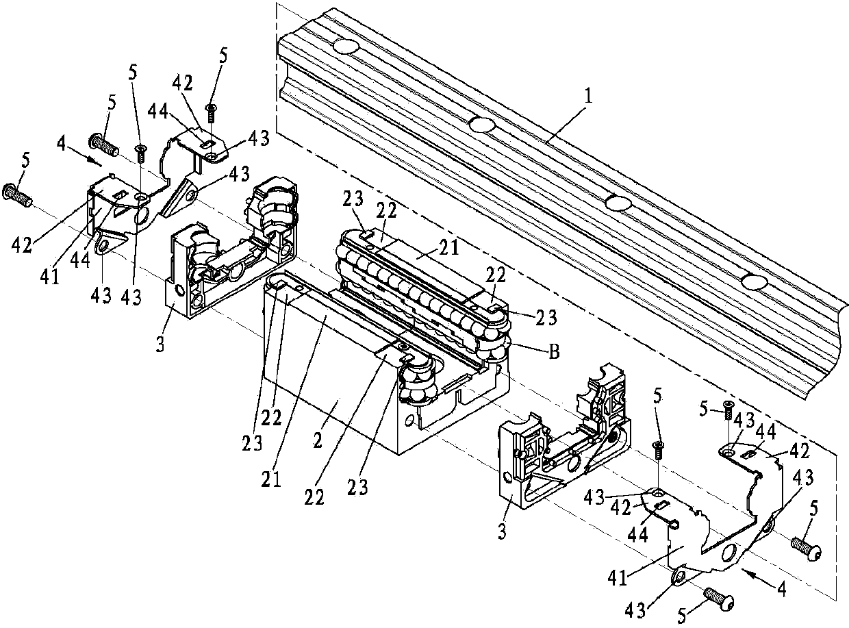
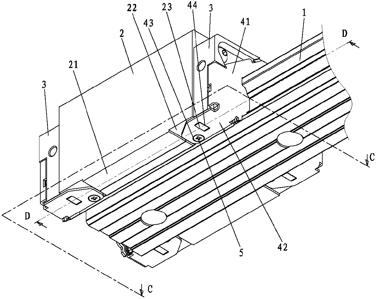
[0036] Please refer to the first embodiment of the present invention figure 1 and figure 2 As shown, this embodiment includes:

[0037] A sliding rail 1; a sliding seat 2, including two relatively extended legs 21 for straddling the sliding rail 1, a recess 22 is respectively arranged at both ends of each leg 21, and each of the recesses 22 At least one protrusion 23 is provided; two end covers 3 are combined on the opposite ends of the slide seat 2; two reinforcement sheets 4, each reinforcement sheet 4 includes a side plate 41, and two curved edges extending from the side plate 41 Bending extension piece 42, the two bending extension pieces 42 correspond to the recesses 22 on the two feet 21 of the slide seat 2, a fixing hole 43 is respectively arranged on the side plate 41 and the two bending extension pi...


PUM


Abstract

The invention discloses a moving part structure of a linear sliding rail. The moving part structure comprises a sliding base, two end covers and two strengthening pieces, wherein the sliding base comprises two foot parts which relatively extend and can stride on the sliding rail; the end covers are combined on the two relative ends of the sliding base; each strengthening piece comprises a side plate and two buckling extending pieces which are corresponding to the two foot parts through extending of the side plate, the two buckling extending pieces are respectively provided with a fixed hole, the two strengthening pieces are respectively combined on the outer sides of the end covers, and the two buckling extending pieces are fixed on the two foot parts of the sliding base when a fixed piece passes through the fixed holes; the two ends of each foot part of the sliding base are respectively provided with at least one lug, the two buckling extending pieces of the two strengthening pieces are respectively provided with at least one clamping part, and the clamping part is correspondingly clamped at the lug. Through the structure, the moving part structure of the linear sliding rail provided by the invention has the advantages that the combining stability is improved, the malfunction probability of a moving part is reduced, the operation speed of the moving part structure is improved, and the service life is prolonged.

Description

technical field [0001] The invention relates to a moving part structure of a linear slide rail, in particular to a linear slide rail which utilizes the locking part of the reinforcing plate to be locked on the protrusion of the slide seat to increase the stability of the combination of the end cover and the slide seat. Movement structure. Background technique [0002] Linear slide rails are widely used in many large precision machinery to improve the precision, smoothness, stability and service life of the sliding parts. [0003] The linear slide rail is composed of a slide rail and a moving part straddling the slide rail. The moving part includes a sliding seat and two end covers. The two end covers are combined with the opposite ends of the sliding seat. The track of the slide rail forms a moving track, the end cover forms a rotary channel to connect the moving track, and the slide seat provides a return channel to connect the rotary channel, so that the moving track, the...

Claims


Application Information

Patent Timeline
Patent Type & Authority Applications(China)
IPC IPC(8): F16C29/04
Inventor 许明哲
Owner CHIEFTECH PRECISION
Why Eureka
Try Eureka