
Method of damage-resistant driving component device and damage-resistant driving component device implementing the same

A driving component and anti-damage technology, applied in the mechanical field, can solve problems such as reducing the service life of equipment, damaging power impact parts, driving mechanisms and other components

Active Publication Date: 2018-06-19
JINING CITY CUSTOMKEY ELECTROMECHANICAL TECH CO LTD
View PDF7 Cites 0 Cited by
  • Summary
  • Abstract
  • Description
  • Claims
  • Application Information

AI Technical Summary

Problems solved by technology

[0002] Existing reciprocating impact mining equipment or the dynamic impact part of the mining mechanism in the reciprocating impact excavation equipment drives the impact head to reciprocate impact. During the impact and blanking process, the impact reaction twist force will seriously damage the dynamic impact part, and even cause the driving mechanism and other The damage of components greatly reduces the service life of the equipment

Method used


Image

  • Method of damage-resistant driving component device and damage-resistant driving component device implementing the same
  • Method of damage-resistant driving component device and damage-resistant driving component device implementing the same
  • Method of damage-resistant driving component device and damage-resistant driving component device implementing the same

Examples


Embodiment 1

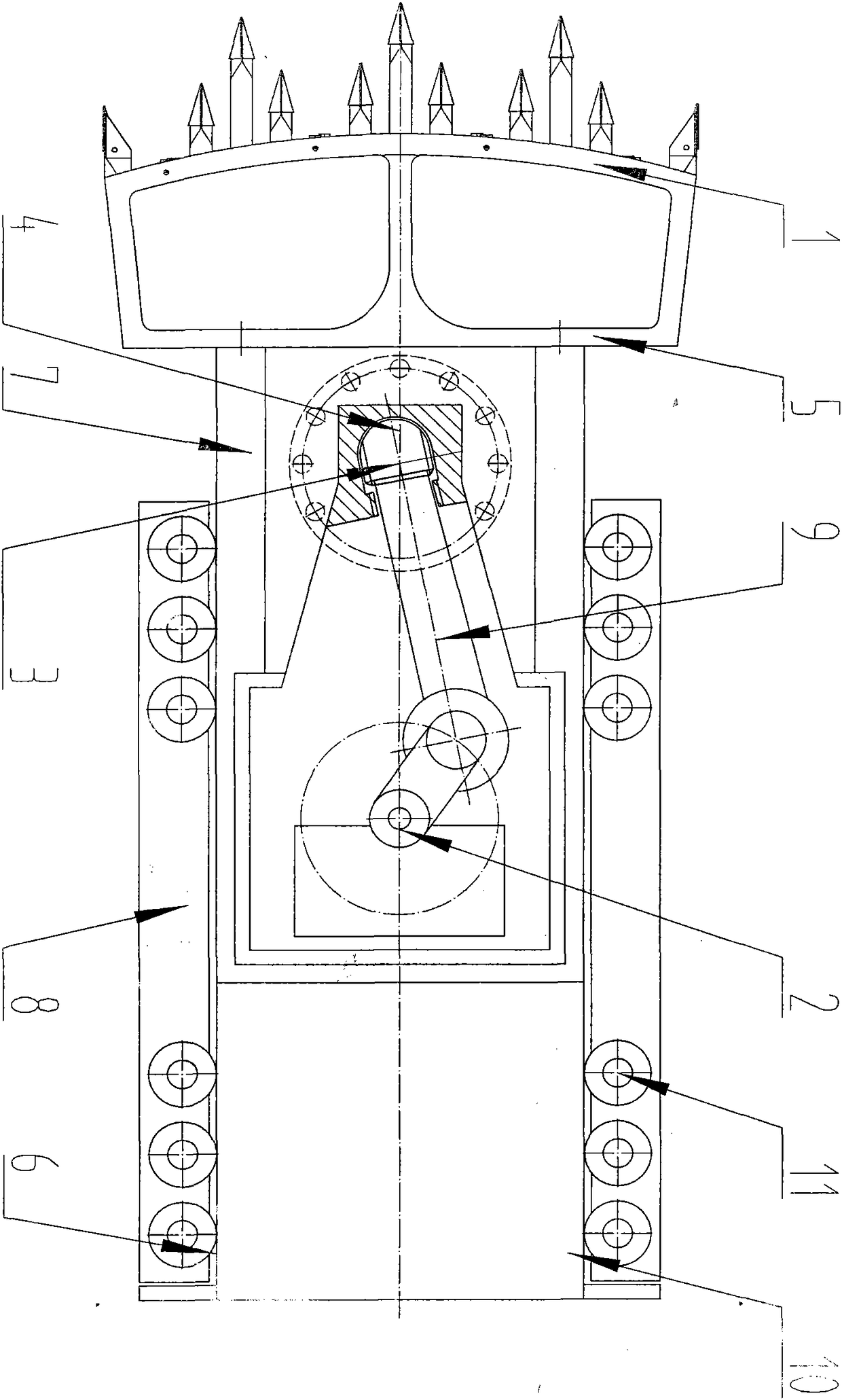
[0165] Such as figure 1As shown, the anti-damage driving component device includes a mining mechanism 1, a driving mechanism 2, and an anti-damage mining driving component mechanism 3. The damage-proof mining driving component mechanism 3 includes an anti-breaking structure 4, and the mining mechanism 1 includes an impact head 5. The device also includes a guide mechanism 6. The guide mechanism 6 includes an impact guide 7 and a guide support 8. One end of the impact guide 7 is provided with an impact head 5. The driving mechanism 2 includes a power impact member 9. The power impact member 9 and the impact guide 7 separate parts, the anti-breaking structure 4 is arranged at one end of the power impact part 9, the power impact part 9 drives the impact head 5 to reciprocate impact, and the impact reaction force is applied to the anti-breaking structure 4, and the anti-breaking structure 4 prevents the driving mechanism 2Subject to separation and / or impact damage.

[0166] In th...

Embodiment 2

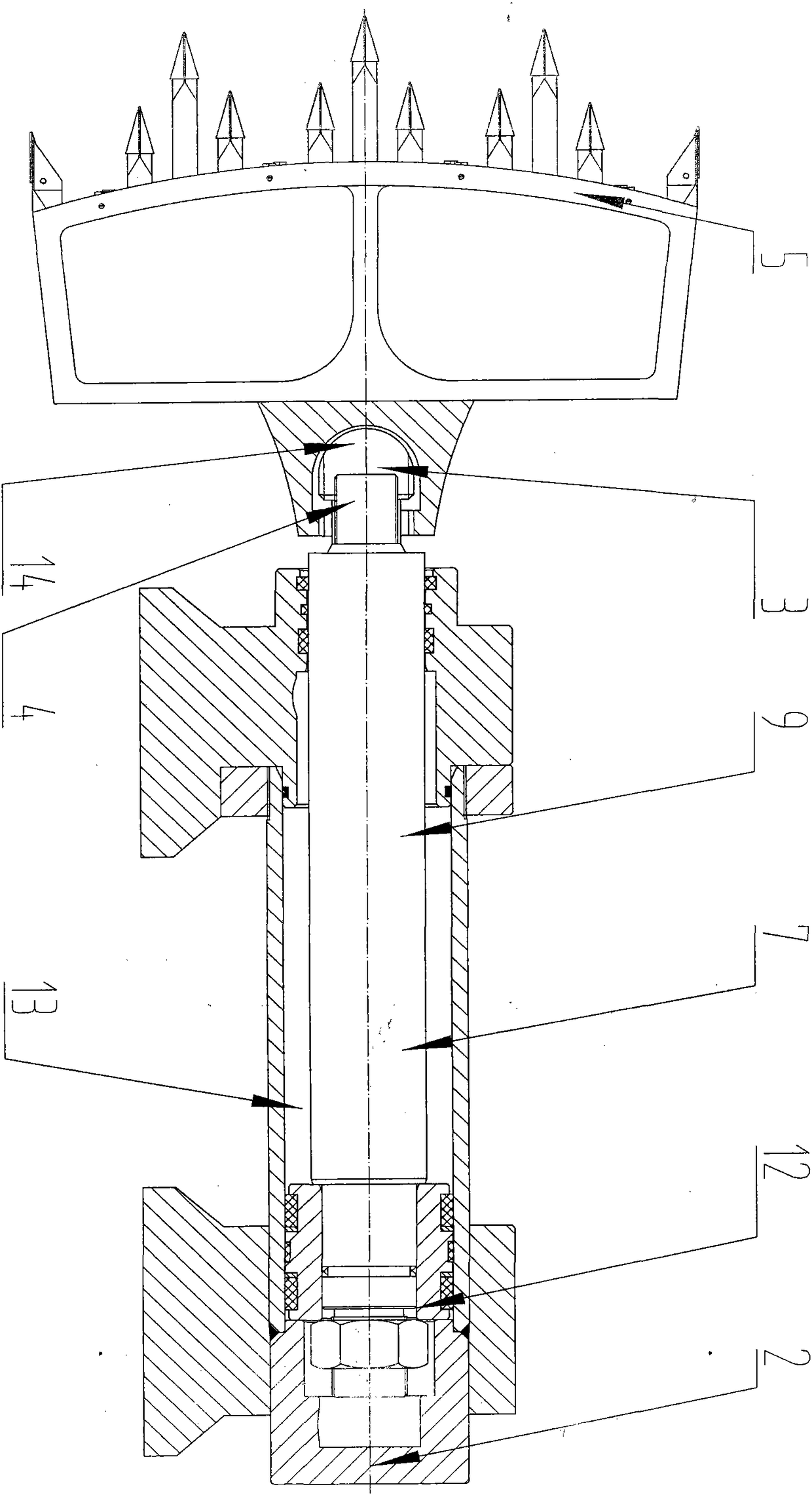
[0174] Such as figure 2 As shown in the anti-damage drive component device, the drive mechanism 2 is a hydraulic impact drive mechanism 12, the hydraulic impact drive mechanism 12 includes a cavity 13, a power impact piece 9, the power impact piece 9 and the impact guide 7 are integrated, and the power impact piece One end of 9 is arranged in the cavity 13, and an anti-damage excavation drive component mechanism 3 is arranged between the other end and the impact head 5. The anti-damage excavation drive component mechanism 3 adopts an anti-break structure 4, which is a rotation-proof structure 4. Break off the structure 14, and rotate the anti-break off structure 14 to rotate under force to protect the connecting rod 29 from being damaged by breaking off.

[0175] The drive mechanism 2 may also adopt a pneumatic impact drive mechanism.

Embodiment 3

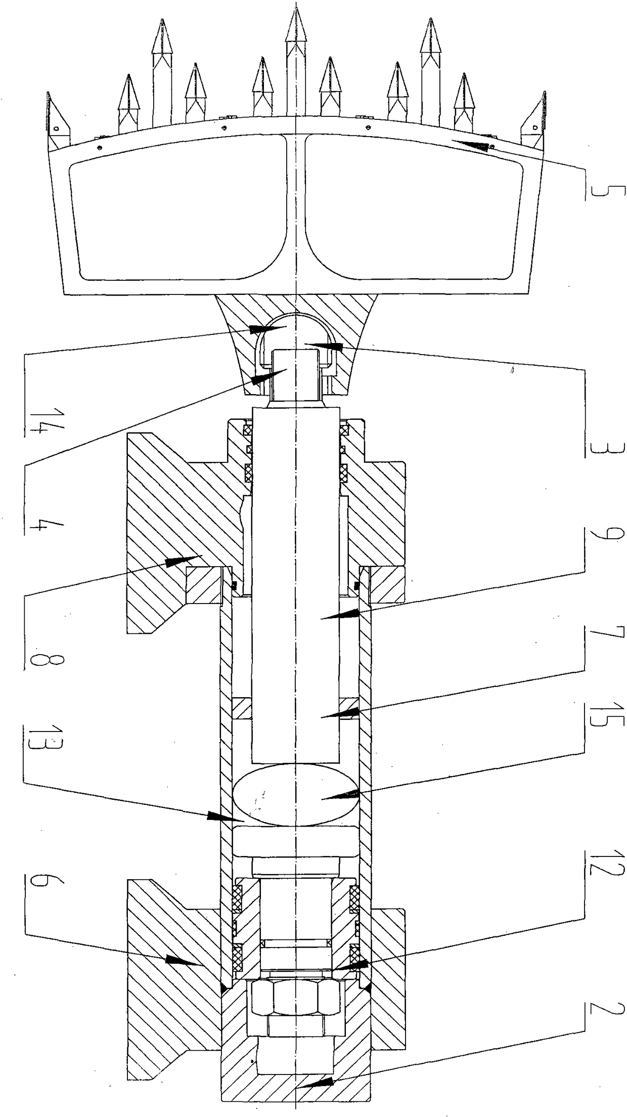
[0177] Such as image 3 As shown in the anti-damage drive component device, the guide mechanism 6 includes an impact guide 7 and a guide support 8, the drive mechanism 2 is a hydraulic impact drive mechanism 12, and the hydraulic impact drive mechanism 12 includes a cavity 13, a power impact member 9, and an air bag 15 , the power impact member 9 and the impact guide 7 are integrated, the air bag 15 is arranged in the cavity 13, one end of the power impact member 9 is arranged in the cavity 13, and an anti-damage mining drive is provided between the other end and the impact head 5. Component mechanism 3, the anti-damage excavation drive component mechanism 3 adopts the anti-break structure 4, the anti-break structure 4 is a rotation and anti-break structure 14, and the rotating anti-break structure 14 is forced to rotate to protect the connecting rod 29 from being damaged by break, The air bag 15 can further slow down the degree of separation damage.

[0178] The drive mechan...


PUM


Abstract

The invention belongs to the field of machinery, and is especially suitable for a method for installing an anti-damage driving part in the field of mining machinery or engineering machinery and an anti-damage driving part device for implementing the method. The device includes a mining mechanism, a driving mechanism, and an anti-damage mining driving part mechanism. , guiding mechanism, etc., the anti-damage excavation drive component mechanism includes an anti-breaking structure and / or a buffering and anti-breaking structure, the mining mechanism includes an impact head, the driving mechanism includes a power impact part, and the anti-damage mining drive part mechanism is arranged on the power impact part One end is set at both ends of the power impact piece or on the power impact piece or on the impact head, the power impact piece drives the impact head to impact, and the impact reaction force is applied to the anti-break structure and / or the cushioning break-proof structure Structurally, the anti-separation structure and / or the cushioning anti-separation structure protects the drive mechanism from separation and / or impact damage.

Description

technical field [0001] The invention belongs to the field of machinery, and is especially suitable for a method for an anti-damage driving component device in the field of mining machinery or construction machinery and the anti-damage driving component device for implementing the method. Background technique [0002] Existing reciprocating impact mining equipment or the power impact part of the excavation mechanism in the reciprocating impact excavation equipment drives the impact head to reciprocate impact. During the impact and blanking process, the impact reaction twist force will seriously damage the power impact part, and even cause the driving mechanism and other The damage of components greatly reduces the service life of the equipment. [0003] In order to solve the above-mentioned problems, the present invention proposes a method of an anti-damage drive component device and a damage-prevention drive component device implementing the method. Contents of the inventi...

Claims


Application Information

Patent Timeline
Patent Type & Authority Patents(China)
IPC IPC(8): E21C35/04E21C31/00
CPCE21C27/12
Inventor 刘素华
Owner JINING CITY CUSTOMKEY ELECTROMECHANICAL TECH CO LTD
Learn More