
Pipeline anti-damage hose clamp with high fastening forces

An anti-damage and fastening force technology, which is applied in the direction of hose connection devices, pipes/pipe joints/fittings, mechanical equipment, etc., can solve problems such as decreased tightening force of hose clamps, scratched or damaged pipes, shortened service life, etc. , to achieve scientific and reasonable structural design, avoid pipeline damage and prolong service life

Inactive Publication Date: 2013-11-13
天津市凯诺实业有限公司
View PDF5 Cites 5 Cited by
  • Summary
  • Abstract
  • Description
  • Claims
  • Application Information

AI Technical Summary

Problems solved by technology

[0003] Throat clamps of this type of structure are more common in daily life, but in actual use, there are still the following problems: 1. With the increase of the use time of the throat clamp, the external vibration will cause the worm and the clamp to punch holes The meshing strength of the hoop is reduced, and the tightening strength of the throat hoop is reduced, which affects the connection of the pipeline, and the leakage of the objects in the pipeline will cause various losses to various degrees; 2. The punching holes punched on the hoop will affect all The connected pipes are scratched or damaged to varying degrees. If it is a hose, the hose wall will be squeezed into the punching hole of the hoop due to the excessive tightening force of the throat hoop, which will affect the later throat Disassembly of the hoop; 3. Since most of the throat hoop hoop is made with punching holes, the stress of the hoop is reduced, the hoop is easy to break, and its service life is shortened

Method used


Image

  • Pipeline anti-damage hose clamp with high fastening forces
  • Pipeline anti-damage hose clamp with high fastening forces
  • Pipeline anti-damage hose clamp with high fastening forces

Examples


Embodiment Construction

[0026] The present invention will be further described in detail below through specific embodiments in conjunction with the accompanying drawings. The following examples are only descriptive, not restrictive, and cannot limit the protection scope of the present invention.

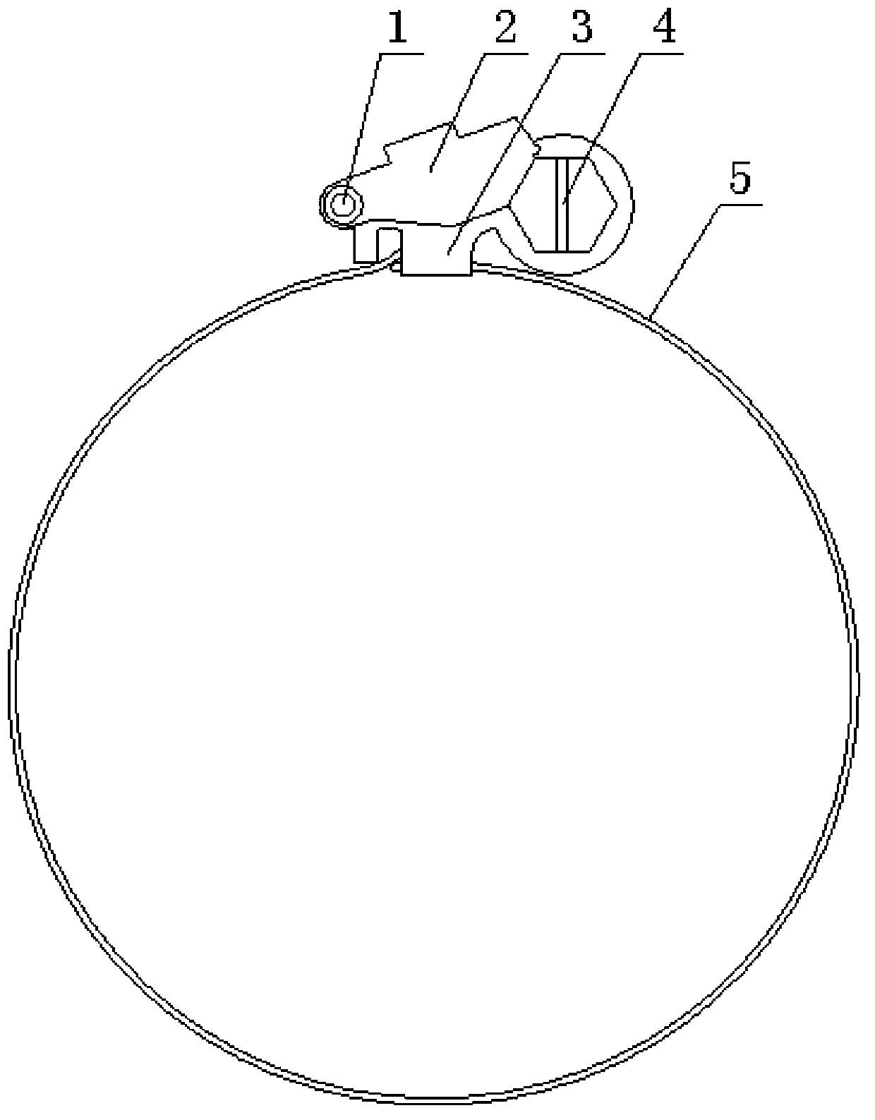
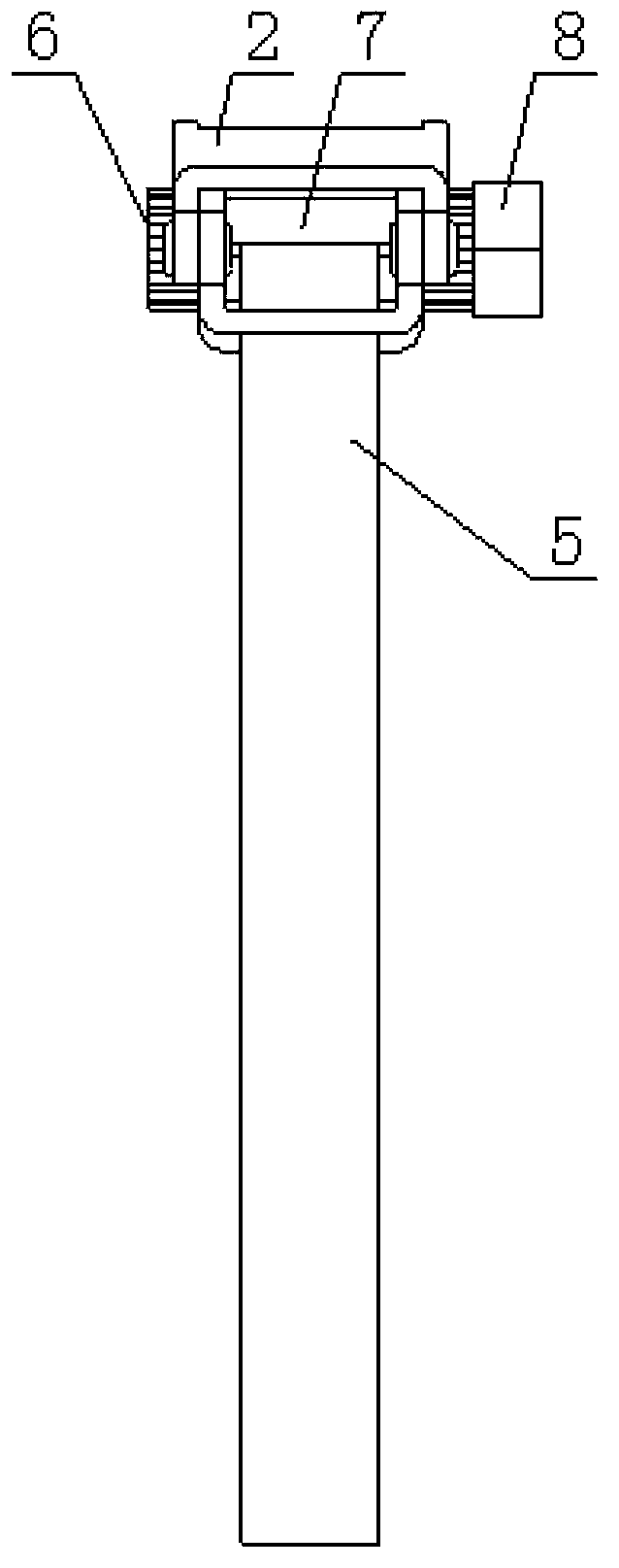
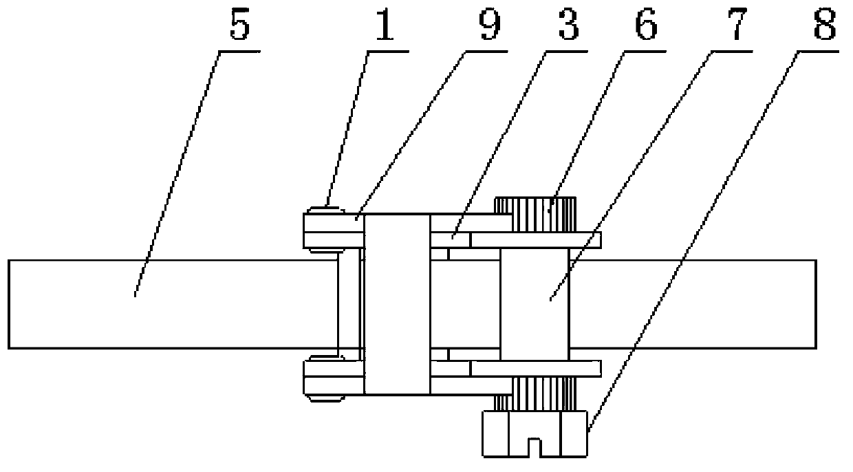
[0027] An anti-damage throat clamp for pipelines with strong fastening force, including a clamp 5, and its innovation is that it also includes a connecting bracket 3, a backstop baffle group 2, a rivet 1, and a tightening rod 4, and the clamp is fixed on the clamp. The connecting bracket is firmly installed at the end, the head of the connecting bracket is shaped on a tightening rod mounting hole 12, and the afterbody of the connecting bracket is shaped on a rivet mounting hole 10, and the screwing rod mounting hole of the connecting bracket is installed. Tighten the rod, on the rod body of the tightened rod, the free end of the strap is axially formed with a slit 13, and the rod body 7 of the tightened rod...


PUM


Abstract

The invention relates a pipeline anti-damage hose clamp with high fastening forces, which comprises a strap and is characterized by further comprising a connecting bracket, a retreat preventing baffle group, rivets and a screwing rod, wherein the connecting bracket is fixedly arranged on the fixed end of the strap; a screwing rod installation hole is formed in the head of the connecting bracket; rivet installation holes are formed in the tail of the connecting bracket; the screwing rod is arranged in the screwing rod installation hole in the connecting bracket; a penetrating seam for a free end of the strap is axially formed in the body of the screwing rod; a meshing fluted disc is arranged on the body of the screwing rod; the retreat preventing baffle group is arranged on the rivet installation holes in the connecting bracket through the rivets; and the retreat preventing baffle group is provided with meshing teeth which are engaged with the meshing fluted disc of the screwing rod. The hose clamp has the advantages of being scientific and reasonable in structure design, high in fastening force, quakeproof, capable of preventing pipeline damage, easy in disassembly, difficult in fracture, long in service life and convenient in use, and is a highly innovative hose clamp.

Description

technical field [0001] The invention relates to a pipeline fastening connector, in particular to a pipeline damage-resistant throat hoop with strong fastening force. Background technique [0002] The throat clamp is a fastener at the joint of the flexible and hard pipe. The appearance of the throat clamp solves the problems of dead angle and liquid and gas leakage when the throat clamp is used for the connection of small-diameter soft and hard pipes in actual operation. The traditional throat hoop is mainly composed of a hoop with punched holes on the surface, a hoop shell and a worm. One end of the hoop is fixed at the bottom of the hoop shell, and the other end of the hoop passes through the inside of the hoop shell and is engaged with the hoop by the worm. The punched holes on the top realize the fastening of the band. [0003] Throat clamps of this type of structure are more common in daily life, but in actual use, there are still the following problems: 1. With the inc...

Claims


Application Information

Patent Timeline
Patent Type & Authority Applications(China)
IPC IPC(8): F16L33/04
Inventor 杜志刚
Owner 天津市凯诺实业有限公司
Learn More