Cable quick connector

A cable and fast technology, which is applied in the direction of cable joints, circuits, connections, etc., can solve the problems of imprecise binding and connection, easy to be exposed to water, etc., achieve the effects of low cost, prolong life, and improve equipment operating time

Active Publication Date: 2016-06-08
乌海包钢矿业有限责任公司
View PDF8 Cites 0 Cited by
  • Summary
  • Abstract
  • Description
  • Claims
  • Application Information

AI Technical Summary

Problems solved by technology

[0003] The purpose of the present invention is to provide a method that can overcome the problems of electric leakage and power connection caused by the imprecise binding and connection of the cable after it is damaged, and is easily affected by water and on-site operating environment factors. , high work efficiency and low production cost cable quick connector

Method used


Image

  • Cable quick connector
  • Cable quick connector
  • Cable quick connector

Examples


Embodiment Construction

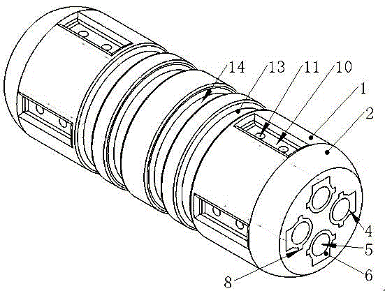
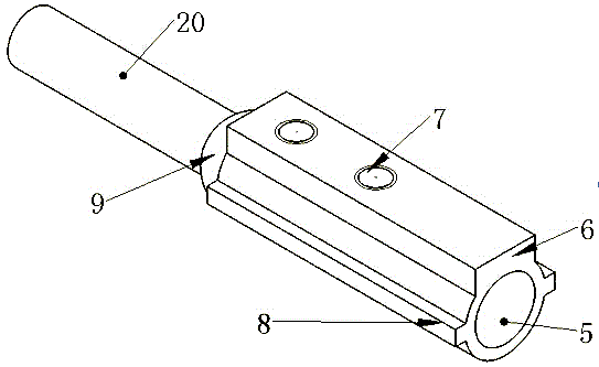
[0029] exist figure 1 In the middle, it is convenient to install on the front end face 2 of the insulating rod 1 and process it into an end face with a certain arc. Both ends of the insulating rod 1 are respectively built with mutually symmetrical cable sockets 4. In order to prevent the cable 18 from being disconnected from the cable socket 4 during the dragging process, a pattern 5 is provided on the inner cavity wall of the cable socket 4 to achieve The purpose of increasing the friction force; one end surface of the cable socket 4 is flush with the end surface of the insulating rod 1, and the other end surface is connected by a connecting cable 20. The cable socket 4 is a hollow metal rod, and the outer wall surface of the cable socket 4 is provided with reinforcement Wall 6, reinforced ribs 8 are respectively provided on both sides of the reinforced wall 6 to ensure that the cable 18 cannot rotate in the cable socket 4, and at the same time, a reinforcing boss is provide...


PUM


Abstract

The invention relates to a cable quick joint, which belongs to the field of engineering power transmission and distribution. The two ends of the insulating rod of the present invention are respectively equipped with symmetrical cable sockets. One end face of the cable socket is flush with the end face of the insulating rod, and the other end is connected by a connecting cable. The cable socket is a hollow metal rod, and the cable socket is provided with a fixed For the threaded hole of the cable, a bolt penetration hole corresponding to the threaded hole is provided on the side wall of the insulating rod, and at least one groove is provided behind the bolt penetration hole. The invention has low cost and wide application range, and is mainly used in power transmission and distribution in mining projects. In harsh environments and narrow spaces, one person can complete the work alone. The invention greatly improves the safety of cables, thereby ensuring The safety of operation, repair and maintenance under various support conditions, especially the protection of personal and equipment.

Description

technical field [0001] The invention relates to a quick cable connector, especially capable of realizing quick cable connection in a relatively complicated working place, and belongs to the field of engineering power transmission and distribution. Background technique [0002] At present, the known cable connection method adopts the two sections of the cable itself to be connected to overlap each other. After repeated twisting and flattening with cable pliers, the electric tape is used to spiral forward and wrap, and then the waterproof tape is spirally wound to wrap the outer layer. In the process At least three people are required to work together, and the wrapped cables are easily affected by various environmental factors on site during the later cable movement process, so that the just wrapped joints will be pulled apart and pierced again, while water and other on-site operating environmental factors It is easy to affect the damaged part, cause cable leakage and power co...

Claims


Application Information

Patent Timeline
Patent Type & Authority Patents(China)
IPC IPC(8): H02G15/18H01R13/52H01R13/627H01R4/42
Inventor 胡艳英黄大江邵玉全王珍涛王杰董占京崔凤郭丽东李强王瑞全齐静
Owner 乌海包钢矿业有限责任公司
Why Eureka
Try Eureka