Pipe connector for connecting two pipe sections

A technology of connectors and pipe sections, applied in the field of heat exchangers, can solve problems such as incorrect assembly of pipe connectors, and achieve the effect of simple assembly

Inactive Publication Date: 2018-10-23
MAHLE INT GMBH
View PDF5 Cites 0 Cited by
  • Summary
  • Abstract
  • Description
  • Claims
  • Application Information

AI Technical Summary

Problems solved by technology

In this case, the problem is that the pipe connectors can initially hold firm during the leak test, and it is not obvious that the pipe connectors have been incorrectly assembled

Method used


Image

  • Pipe connector for connecting two pipe sections
  • Pipe connector for connecting two pipe sections
  • Pipe connector for connecting two pipe sections

Examples


Embodiment Construction

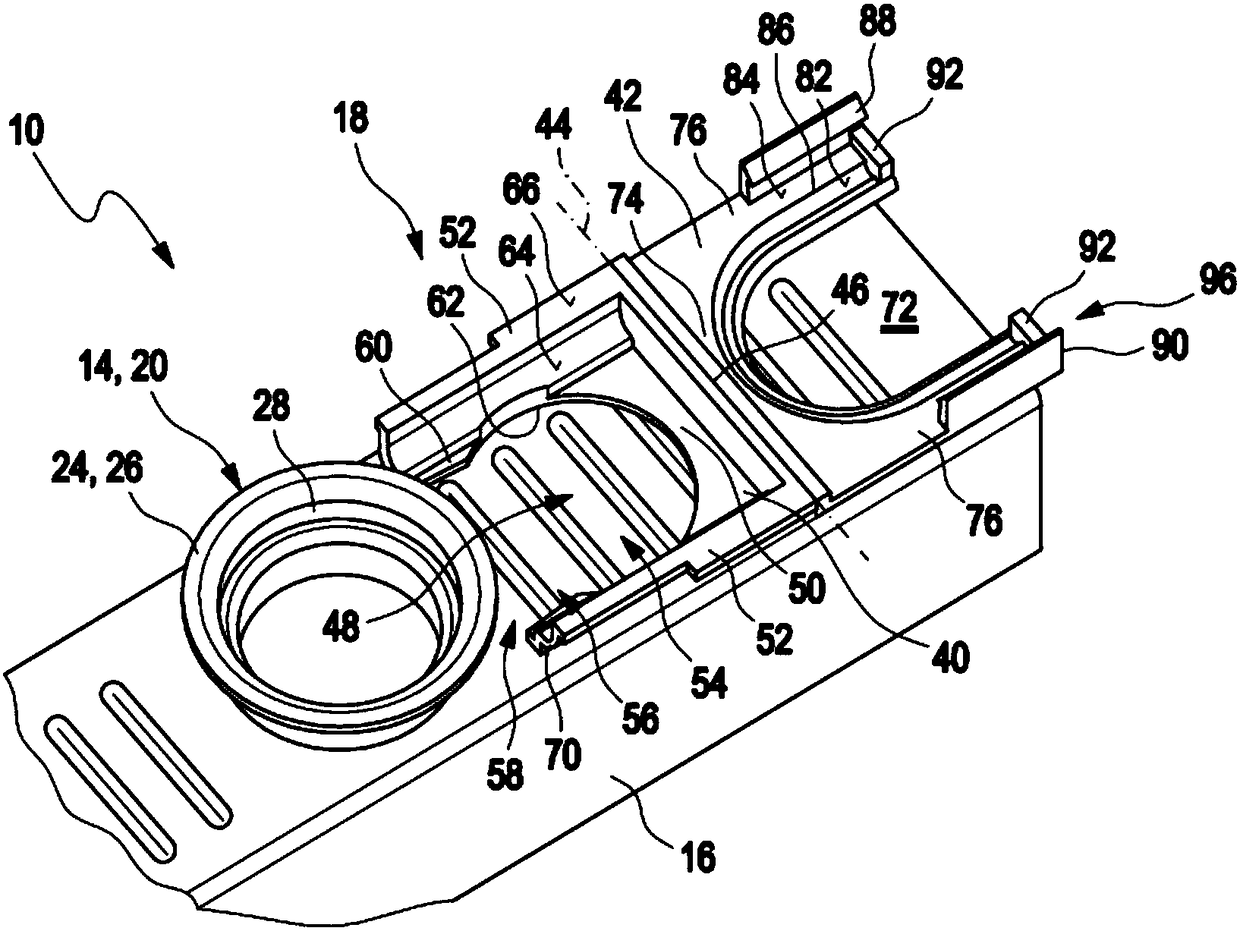
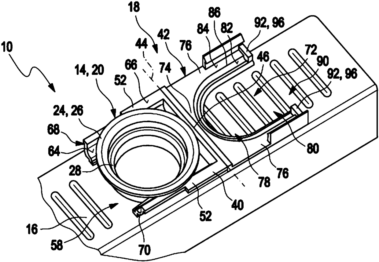
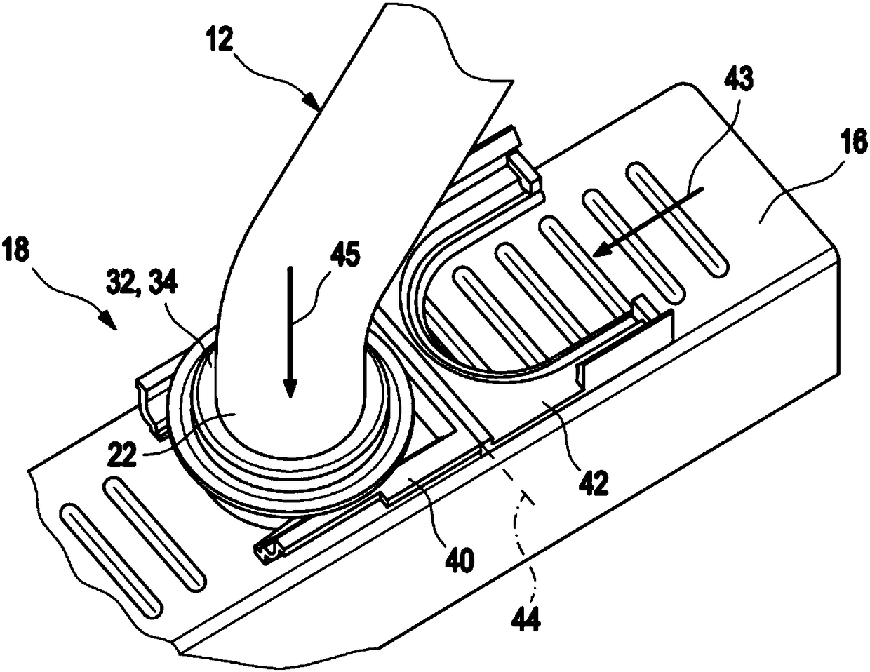
[0035] exist Figure 1 to Figure 5The embodiment of the tube connection 10 shown in can be used, for example, to connect a tube 12 , such as a feed tube, to a tube assembly 14 of a heat exchanger 16 . The pipe connection 10 has a pipe connector 18 which connects a first pipe section 20 with a second pipe section 22 . The first pipe section 20 corresponds to the tube assembly 14 of the heat exchanger 16 and the second pipe section 22 corresponds to the tubes 12 .

[0036] The first pipe section 20 has a connecting flange 24 which preferably has a connection 26 extending in its circumferential direction. A ring joint 26 is arranged at the free end of the pipe section 20 . A radially flared area 28 extending outwardly from the annular joint 26 is designed to receive a sealing element 30 .

[0037] The second pipe section 22 has a connecting flange 32 which preferably has the form of a collar 34 and is located at a distance from an end 36 of the second pipe section 22 . This f...


PUM


Abstract

The invention relates to a pipe connector (18) for connecting a first pipe section (20) and a second pipe section (22), each of which has a connecting flange ()24, 32. In order to render incorrect assembly of the pipe connector evident, it is suggested that the pipe connector (18) has a lower motion link (40) and an upper motion link (42), which are retained so as to be pivotable towards one another about a pivot axis (44), that the lower motion link (40) has a lower seating (48) for one of the pipe sections (20, 22), that the lower motion link (40) has a bearing surface (66) for the connection flange (24) of the first pipe section (20), that the upper motion link (42) has an upper seating (72) for the other of the pipe sections (22), that the upper motion link (42) has a bearing surface (82) for the connection flange (32) of the second pipe section (22), that the pivot axis (44) extends substantially at right angles to an axial direction of the lower seating (48) and the upper seating(72) for the pipe sections (20, 22), and that in a closed state the bearing surface (66) of the lower motion link (40) faces the bearing surface (82) of the upper motion link (42), so that the connection flanges (24, 32) of the two pipe sections (20, 22) can be clasped.

Description

technical field [0001] The invention relates to a pipe connector for connecting a first pipe section and a second pipe section, the pipe sections each having a connecting flange. The invention further relates to a pipe connection using such a pipe connector. Furthermore, the invention relates to a heat exchanger having at least one such tube connection. Background technique [0002] Such pipe connectors are known in the prior art and are used to fasten pipe sections inserted into each other. A pipe connector typically has two legs fastened at a hinge for pivoting towards each other about a pivot axis extending parallel to the plugging direction in which the two pipe sections are inserted into each other. At the same time, the equal legs buckle the connecting flanges of the two pipe sections so that the pipe sections are firmly held. Thus, the leg and the flange form a type of wedge gear by means of which the axial holding force can be achieved. The two legs must be faste...

Claims


Application Information

Patent Timeline
Patent Type & Authority Applications(China)
IPC IPC(8): F16L23/024F28F9/26
CPCF16L23/024F28F9/26F16L37/1225F28F9/0248F28F9/0258F16L23/04F16L25/06F16L37/144F16L2201/00
Inventor 佩尔松·埃迪
Owner MAHLE INT GMBH
Why Eureka
Try Eureka