water spray cleaning tool
What is Al technical title?
Al technical title is built by PatSnap Al team. It summarizes the technical point description of the patent document.
A technology for cleaning tools and nozzles, applied in the field of cleaning appliances, can solve the problems of only one rod for one use, inconvenient operation, inability to replace the type of wiper head, etc., and achieves the effect of saving materials and convenient operation.
Active Publication Date: 2016-01-06
JIAXING JACKSON TRAVEL PROD CO LTD
View PDF6 Cites 0 Cited by
Summary
Abstract
Description
Claims
Application Information
AI Technical Summary
This helps you quickly interpret patents by identifying the three key elements:
Problems solved by technology
Method used
Benefits of technology
Problems solved by technology
[0002] At present, in the water spray cleaning tools sold on the market, the water storage device is located on one side of the wiper head. According to the principle of leverage, the closer the water storage position is to the wiper head, the more difficult the operation is. The water spray device is pressurized and sprayed once. , unable to spray water continuously, inconvenient to operate, and only one rod can be used, and the type of wiping head cannot be replaced
Method used
Image
Click on the blue label to locate the original text in one second.
Reading with bidirectional positioning of images and text.
Examples
Embodiment 1
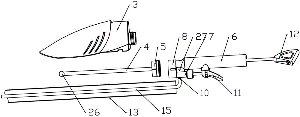
[0022] like Figure 1-4 As shown, the water spray cleaning tool provided in this embodiment includes a wiping head 1, a hollow connecting rod, a handle 2, a water storage tank 3 and a water spraying device, the wiping head 1 is threadedly connected with the hollow connecting rod, and the handle 2 Connected with the other end of the hollow connecting rod, the water storage tank 3 is located at one end close to the handle 2, the water storage tank 3 is provided with a water suction pipe 4, and the water suction pipe 4 is connected with the bottle cap 5 on the water storage tank connected, the water spray device includes a booster pump 6, an outlet pipe 7, a connector 8, a drainage pipe and a nozzle 9, one end of the connector 8 is connected with the booster pump 6 and the outlet pipe 7, and the other end of the connector 8 One end is connected with the bottle cap 5, the booster pump 6, the water outlet pipe 7 are connected with the water storage tank 3, one end of the drainage p...
Embodiment 2
[0032] Replace the wiping head with a mop head, and other structures are the same as those in Example 1, realizing the multi-purpose purpose of one rod. Because the water storage tank 3 is arranged on one side of the handle 2, the mop head can be deep into the bottom of the sofa. Solved the problem of wiping dead corners.
PUM
Abstract
The invention discloses a water spraying cleaning tool which comprises a scrubbing head, a hollow connecting rod, a handle, a water storage tank and a water spraying device. The scrubbing head is in threaded connection with the hollow connecting rod, the handle is connected with the other end of the hollow connecting rod, the water storage tank is arranged at the end, near the handle, of the hollow connecting rod, the water spraying device comprises a pressure pump, a water outlet pipe, a connector, a drainage pipe and a nozzle, one end of the connector is connected with the pressure pump and the water outlet pipe, the other end of the connector is connected with a bottle cap, one end of the drainage pipe is communicated with the water outlet pipe, the other end of the drainage pipe is communicated with the nozzle, the drainage pipe is arranged inside the hollow connecting rod, a water outlet valve is arranged at the connecting position of the drainage pipe and the water outlet pipe, a water outlet valve trigger is arranged on the water outlet pipe, and a pressurized handle is arranged on the pressure pump. The water spraying cleaning tool has the advantages that due to the fact that the water storage tank is arranged at the end, near the handle, of the hollow connecting rod, more effort is saved during the operation process, the function of continuous water spraying can be achieved for each time of pressurizing, operation is convenient and practical, the scrubbing head can be replaced, and materials are saved.
Description
technical field [0001] The invention belongs to the technical field of cleaning appliances, in particular to a water spray cleaning tool. Background technique [0002] At present, in the water spray cleaning tools sold on the market, the water storage device is located on one side of the wiper head. According to the principle of leverage, the closer the water storage position is to the wiper head, the more difficult the operation is. The water spray device is pressurized and sprayed once. , cannot spray water continuously, it is inconvenient to operate, and it can only be used with one rod, and the type of wiping head cannot be replaced. Contents of the invention [0003] The technical problem to be solved by the present invention is to provide a water spray cleaning tool that is easy to use, labor-saving to operate, and has multiple functions with one rod. [0004] In order to solve the above-mentioned technical problems, the water spray cleaning tool provided by the pre...
Claims
Application Information
Patent Timeline
Application Date:The date an application was filed.
Publication Date:The date a patent or application was officially published.
First Publication Date:The earliest publication date of a patent with the same application number.
Issue Date:Publication date of the patent grant document.
PCT Entry Date:The Entry date of PCT National Phase.
Estimated Expiry Date:The statutory expiry date of a patent right according to the Patent Law, and it is the longest term of protection that the patent right can achieve without the termination of the patent right due to other reasons(Term extension factor has been taken into account ).
Invalid Date:Actual expiry date is based on effective date or publication date of legal transaction data of invalid patent.