Roll gap positioning mechanism of front pinch roll

A positioning mechanism and pinch roller technology, which is applied in the field of metal strip recoiling inspection unit equipment, can solve the problems of strip scratches, tape heads are difficult to pass through the pinch roller at the beginning, and tension is unstable, so as to avoid scratches and increase Large opening, easy to wear the belt

Inactive Publication Date: 2015-06-17
CHINA NAT HEAVY MACHINERY RES INSTCO
View PDF8 Cites 0 Cited by
  • Summary
  • Abstract
  • Description
  • Claims
  • Application Information

AI Technical Summary

Problems solved by technology

When the upper uncoiling is linked, the upper pinch steering roller is lifted up to act as a steering roller. The wrap angle of the strip at the steering roller is too small, resulting in unstable tension and scratches on the surface of the strip; if in order to increase this Reduce the lifting stroke of the upper pinch turning roller by reducing the wrap angle at the center, which will cause the irregular belt head to be difficult to pass through the pinch roller at the beginning

Method used


Image

  • Roll gap positioning mechanism of front pinch roll
  • Roll gap positioning mechanism of front pinch roll

Examples


Embodiment Construction

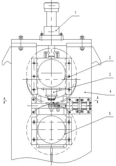
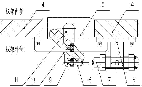
[0012] Such as figure 1 and figure 2 As shown, a first pinch roller gap positioning mechanism is characterized in that it comprises a bracket 6, an air cylinder 7, a joint 8, a movable pin shaft 9, a connecting rod 11, and a fixed pin shaft 10. The positioning mechanism is located on the upper and lower clamps. Between the bearing housings of the steering roller, and installed on the outside of the frame 4 by bolt connection, the cylinder 7 is installed on the bracket 6, one end of the joint 8 is threaded with the cylinder 7, and the other end is connected with the active end of the connecting rod 11 through a movable pin The shaft 9 is connected. The intermediate position of the connecting rod 11 is connected with the bracket 6 through the fixed pin shaft 10. When the piston rod of the cylinder 7 extends, the driven end of the connecting rod 11 is located at the center of the upper surface of the lower pinch steering roller bearing seat, and the connecting rod 11 can swing ar...


PUM

PropertyMeasurementUnit
thicknessaaaaaaaaaa

Abstract

The invention is applied on metal strip rewinding inspection machine group equipment, and particularly relates to a roll gap positioning mechanism of a front pinch roll. The roll gap positioning mechanism is characterized by comprising a support, an air cylinder, a connector, a moving pin shaft, a connecting rod and a fixed pin shaft, wherein the positioning mechanism is arranged between upper and lower pinch turning roll bearing bases and is arranged on the outer side of a rack through a bolt connecting manner; the air cylinder is arranged on the support, one end of the connector is in threaded connection with the air cylinder, and the other end of the connector is connected with the driving end of the connecting rod through the moving pin shaft; the middle position of the connecting rod is connected with the support through the fixed pin shaft, when the piston rod of the air cylinder stretches out, the driven end of the connecting rod is positioned on the center position of the upper surface of the lower pinch turning roll bearing base, and the connecting rod can swing around the fixed pin shaft. The roll gap positioning mechanism provided by the invention meets different requirements on the roll gap of the front pinch roll when a unit is subjected to tape threading and linkage, a wrap angle of the front pinch roll of the strip is increased in upper uncoiling linkage, the strip is prevented from being scratched, the movement of the positioning mechanism is flexible, and a clamping phenomenon does not exist.

Description

Technical field [0001] The invention relates to the technical field of metal strip rewinding inspection unit equipment, in particular to a roll gap positioning mechanism for a pinch roll at the beginning. Background technique [0002] At present, the beginning pinch rollers used in most recoiling units need to meet the requirements of both upper and lower uncoiling due to the uncertainty of the unit's incoming steel coils. The pinch roller at the beginning is mainly composed of the frame, the upper pinch steering roller, the lower pinch steering roller, the gap adjustment pad, the hydraulic cylinder and the transmission device. The lower pinch steering roller is fixed on the frame, and the upper pinch steering roller The rollers are driven up and down by hydraulic cylinders. When the unit is threading the belt, the hydraulic cylinder drives the upper pinching steering roller to press down, and the clamping strip is fed forward. When the upper unwinding is linked, the upper pinc...

Claims


Application Information

Patent Timeline
Patent Type & Authority Patents(China)
IPC IPC(8): B21C47/26B21C47/34
Inventor 靳恩辉王鹏马兰松任玉成卢进莉
Owner CHINA NAT HEAVY MACHINERY RES INSTCO
Why Eureka
Try Eureka