Guiding locating structure

A technology of guiding positioning and positioning grooves, which is applied in the direction of workpiece clamping devices and manufacturing tools, can solve the problems of complex positioning process, poor positioning accuracy, and non-quantitative translation, and achieve the effect of simple positioning and high accuracy

Inactive Publication Date: 2013-11-27
WUXI CITY NEW DISTRICT WEICHUANGLI MOLD FACTORY
View PDF0 Cites 0 Cited by
  • Summary
  • Abstract
  • Description
  • Claims
  • Application Information

AI Technical Summary

Problems solved by technology

[0002] The existing guide positioning structure is generally a track structure, but the translation of this structure cannot be quantified, which generally requires m

Method used


Image

  • Guiding locating structure

Examples


Embodiment Construction

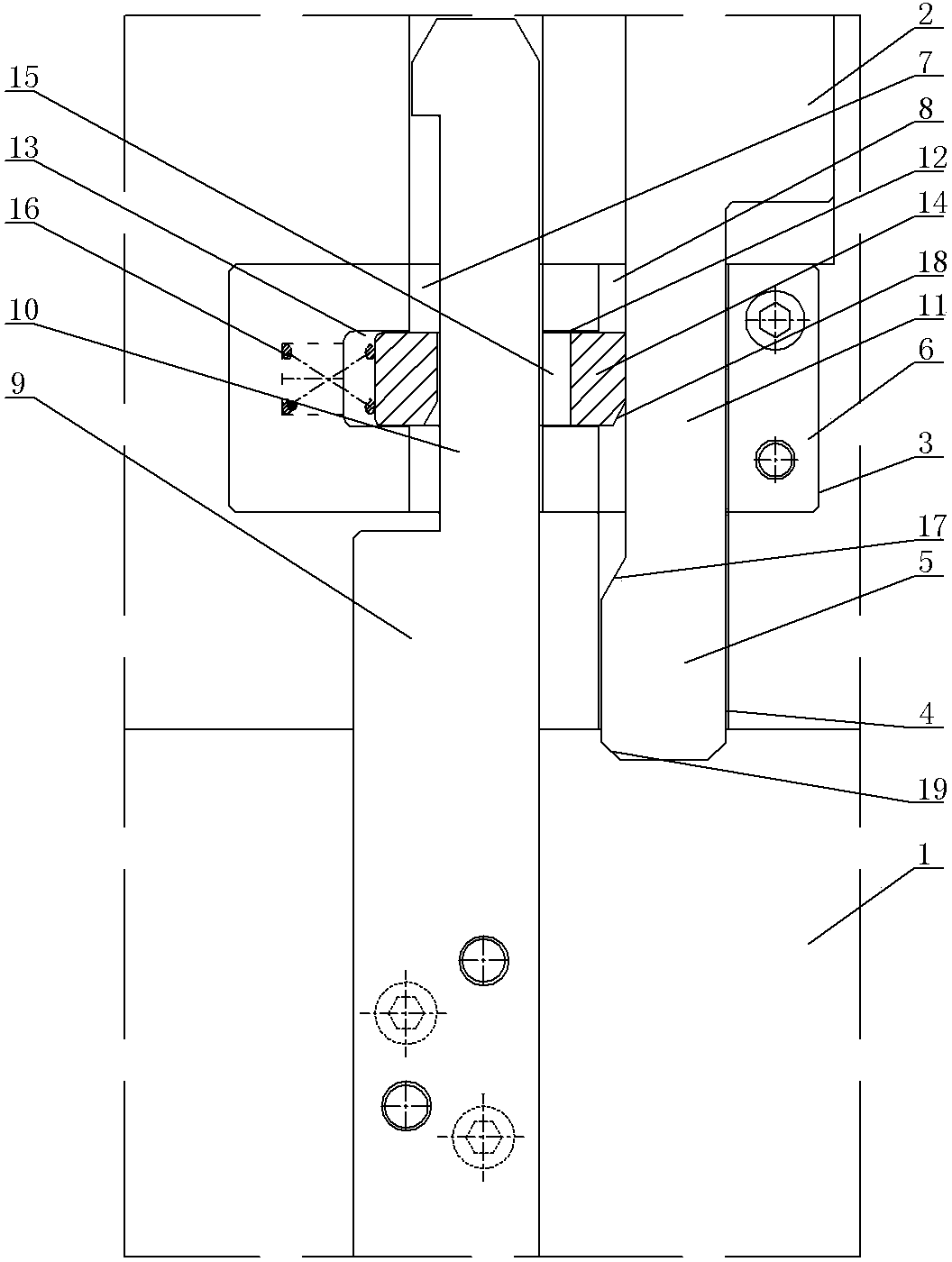
[0007] See figure 1 , which includes a fixed base plate 1, a moving block 2, a cavity 3 and a moving block positioning groove 4 are opened in the middle of the fixed base plate 1, the end part 5 of the moving block 2 is placed in the moving block positioning groove 4, and a guide is installed in the cavity 3 Block 6, the guide block 6 is provided with two parallel guide cavities 7, 8, the upper guide end 10 of the guide column 9 is installed in the guide cavity 7 on one side, and the lower positioning end of the guide column 9 is fastened to the fixed base plate 1, The lower guide part 11 of the moving block 2 is housed in the guide cavity 8 on the other side, and the middle positions of the two guide cavities 7 and 8 are provided with a communicating limiting groove 12, which corresponds to the position of the guiding cavity 7 on one side. The side wall has a corresponding positioning groove 13, and the positioning block 14 is sleeved on the upper guide end 10 of the guide co...


PUM


Abstract

The invention provides a guiding locating structure which enables movement to be conducted in a quantitative mode. After movement is in place, manual location again is not required. Location is simple, and accuracy is high. The guiding locating structure comprises a fixed base plate and a movable block and is characterized in that an empty cavity and a movable block locating groove are formed in the middle of the fixed base plate, the tail end portion of the movable block is arranged in the movable block locating groove, a guiding block is arranged in the empty cavity, two parallel guiding cavities are arranged in the guiding block, the upper guiding end of a guiding column is arranged in a guiding cavity on one side, the lower locating end of the guiding column is fastened on the fixed base plate, and a lower guiding portion of the movable block is arranged in a guiding cavity on the other side. A communicated limit groove is formed in the middle position between the two guiding cavities, a locating groove is formed in the limit groove at the position of the lateral wall corresponding to the guiding cavity of one side, a locating block is sleeved on the upper guiding end of the guiding column, and two ends of the locating block are supported on the limit groove and the locating groove respectively.

Description

technical field [0001] The invention relates to the technical field of mechanical structures, in particular to a guiding and positioning structure. Background technique [0002] The existing guide positioning structure is generally a track structure, but the translation of this structure cannot be quantified, which generally requires manual insertion of the positioning structure after moving to a specific position, which makes the positioning process complicated and the positioning accuracy is poor. Contents of the invention [0003] The invention provides a guiding and positioning structure, which enables the movement to be carried out quantitatively, and after the movement is in place, manual repositioning is not required, and the positioning is simple and accurate. [0004] A guiding and positioning structure, the technical solution of which is as follows: it includes a fixed base plate and a moving block, and is ...

Claims


Application Information

Patent Timeline
IPC IPC(8): B25B11/00
Inventor 吕应军
Owner WUXI CITY NEW DISTRICT WEICHUANGLI MOLD FACTORY
Why Eureka
Try Eureka