Vortex compressor manufacture

The technology of a scroll compressor and a manufacturing method, which is applied to rotary piston type machinery, rotary piston type/swing piston type pump parts, mechanical equipment, etc., can solve the problems of increasing the number of assembly processes, and achieve easy positioning and simple positioning. Effect

Inactive Publication Date: 2006-06-28
SANYO ELECTRIC CO LTD
View PDF0 Cites 0 Cited by
  • Summary
  • Abstract
  • Description
  • Claims
  • Application Information

AI Technical Summary

Problems solved by technology

[0005] However, in any manufacturing method, there is an assembly operation in which parts are superimposed, so the number of assembly steps increases, which requires more time in the production of scroll compressors

Method used


Image

  • Vortex compressor manufacture
  • Vortex compressor manufacture
  • Vortex compressor manufacture

Examples


Embodiment Construction

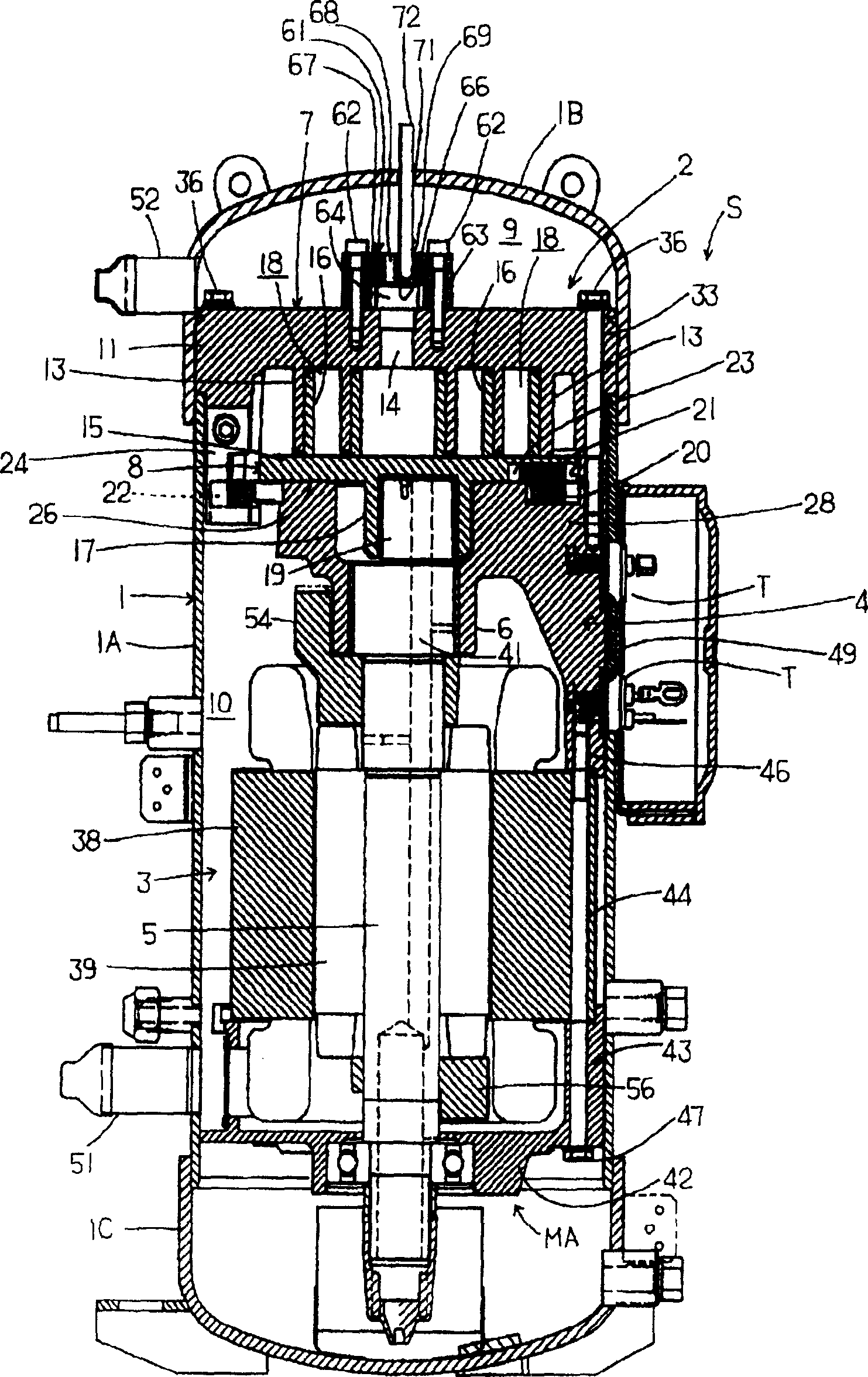
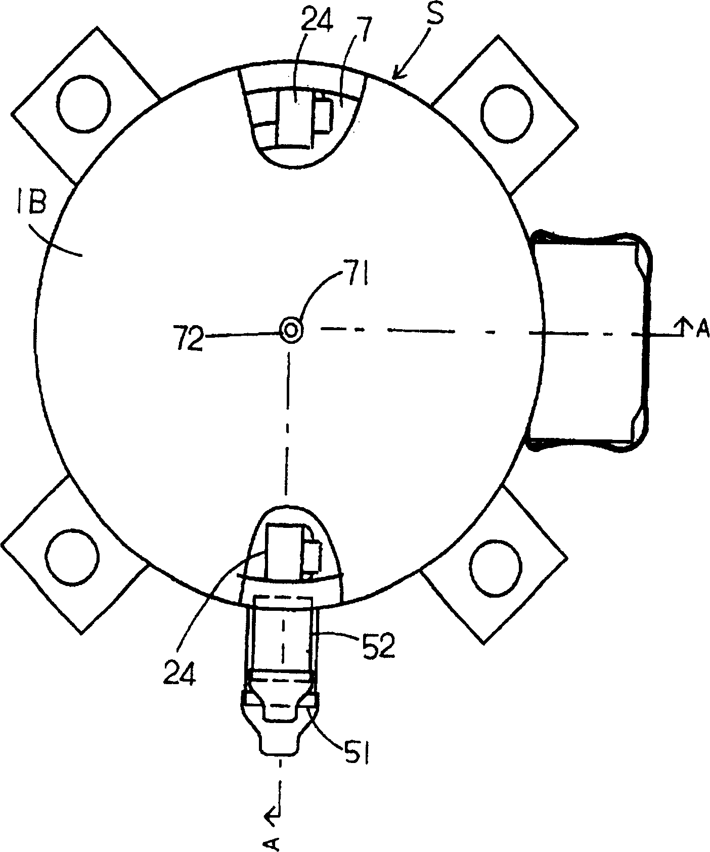
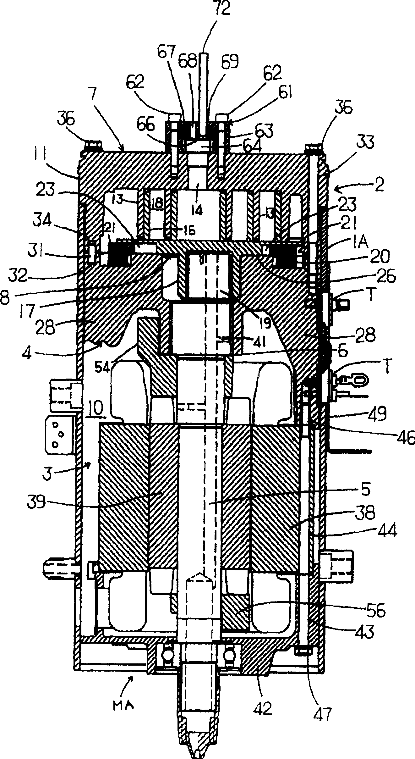
[0021] Hereinafter, embodiments of the present invention will be described in detail with reference to the drawings. figure 1 It is a longitudinal sectional side view (along figure 2 The profile of the A-A line), figure 2 yes figure 1 A cut-away top view of the scroll compressor S, image 3 It is a longitudinal sectional side view of the scroll compressor S with the end cover 1B and the bottom cover 1C of the airtight container 1 removed, Figure 4 yes image 3 Top view of the scroll compressor S, Figure 5 yes figure 1 The front view of the terminal T portion of the scroll compressor S, Figure 6 From Figure 4 The top view of the state in which the scroll compression element 2 is removed, Figure 7 yes figure 1 A longitudinal sectional side view of the scroll compression element 2 of the scroll compressor S, Figure 8 yes Figure 7 Bottom view of the scroll compression element 2, Figure 9 yes figure 1 The longitudinal sectional side view of the motor element ...


PUM


Abstract

The invention provides a method of manufacturing a scroll compressor. A scroll compressing element 2, a motor driving element 3, a support frame 4 having a bearing portion 6 for journaling one end side of a rotary shaft 5 of the motor driving element 3 in the center thereof, and an assembly MA of a sub-bearing 42 for journaling the other end side of the rotary shaft 5 are previously assembled to be integral. The scroll compressing element 2 comprising a fixed scroll 7 with a swirl lap erected on one surface of an end plate thereof; and an oscillating scroll 8 with a swirl lap erected on the other surface of the end plate, rotating around the fixed scroll by drive of the motor driving element, and the like are previously assembled to be integral. After the assembly MA is fixed in a body 1A of a closed container, the scroll compressing element 2 is attached to the assembly MA.

Description

technical field [0001] The invention relates to a manufacturing method of a scroll compressor in which a fixed scroll and an oscillating scroll are engaged with each other for compression. Background technique [0002] The general scroll compressor structure in the past includes a fixed scroll with an end plate with a scroll-shaped cover plate composed of involutes erected on the surface; a scroll-shaped cover composed of involutes erected on the surface plate, and an end plate with a pair of key grooves on the back, and an oscillating scroll that cooperates with the above-mentioned fixed scroll; the multiple compression spaces formed by the oscillating scroll and the fixed scroll are sequentially reduced from the outside to the inside. The electric element that makes the swinging scroll rotate relative to the fixed scroll in a compressed way; has a pair of keys that match the key grooves of the above-mentioned swinging scroll and makes the above-mentioned swinging scroll re...

Claims


Application Information

Patent Timeline
IPC IPC(8): F04C18/02F04C23/02F04C29/00
Inventor 杉本和禧清川保则登义典
Owner SANYO ELECTRIC CO LTD
Why Eureka
Try Eureka