Mold-closing positioning structure of slide block

A technology of positioning structure and positioning block, applied in the direction of coating, etc., can solve the problems of not guaranteeing the injection quality of the product, affecting the accuracy of the cavity in the mold, wear, etc., to avoid wear, ensure the injection quality, and ensure the effect of precision.

Inactive Publication Date: 2013-11-27
WUXI CITY NEW DISTRICT WEICHUANGLI MOLD FACTORY
View PDF0 Cites 2 Cited by
  • Summary
  • Abstract
  • Description
  • Claims
  • Application Information

AI Technical Summary

Problems solved by technology

[0002] The core-pulling of the existing side row inserts relies on the translation of the row blocks to drive the row inserts to complete the core-pulling. When the mold is closed, the row blocks need to be reset. It is to push the row block until it cannot be pushed. In this process, the row insert will inevitably contact with other parts and wear out. Over time, it will affect the accuracy of the cavity in the mold and cannot guarantee the injection quality of the product.

Method used


Image

  • Mold-closing positioning structure of slide block

Examples


Embodiment Construction

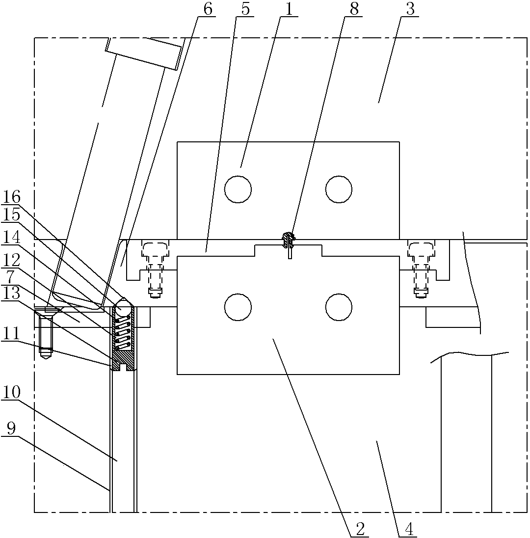
[0007] See figure 1 , which includes front mold 1, rear mold 2, A board 3, B board 4, row position insert 5, row position block 6, wear-resistant block 7, front die 1, rear die 2, row position insert 5 It is a cavity 8, the tail of the row insert 5 is fastened to the row block 6, the row block 6 is supported on the wear-resistant block 7, and the wear-resistant block 7 is fastened to the B plate 4, and the B plate 4 is provided with a thread for positioning hole 9, the upper part of the threaded positioning hole 9 runs through the corresponding position of the wear-resistant plate 7, and the positioning stud 10 is threaded in the threaded positioning hole 9 from bottom to top, and the upper end of the positioning stud 10 is spaced from the upper end surface of the threaded positioning hole 9. There is a cavity 11, the cavity 11 is provided with a support column 13 with a hole 12 in the center, the bottom of the support column 13 is nested and positioned with the upper end of t...


PUM


Abstract

The invention provides a mold-closing positioning structure of a slide block. Through the mold-closing positioning structure, the slide block is pushed to a preset position and is positioned so that a slide insert does not contact with other front parts, wear is avoided, a precision of an inner cavity of a mold is guaranteed and product injection molding quality is guaranteed. The mold-closing positioning structure comprises a front mold, a rear mold, an A plate, a B plate, the slide insert, a slide block and a wear block. A cavity is formed among the front mold, the rear mold and the slide insert. The tail part of the slide insert is fixedly connected to the slide block. The slide block is supported by the wear block. The wear block is fastened to the B plate. The mold-closing positioning structure is characterized in that the B plate is provided with a screw thread positioning hole; the upper part of the screw thread positioning hole passes through the corresponding position of the wear block; a positioning bolt is in a threaded connection relationship with the interior of the screw thread positioning hole from bottom to top; space is formed between the upper end of the positioning bolt and the upper end surface of the screw thread positioning hole; and a support pillar with a central slotted hole is arranged in the space.

Description

technical field [0001] The invention relates to the structural technical field of product molds, in particular to a mold clamping and positioning structure for row position blocks. Background technique [0002] The core-pulling of the existing side row inserts relies on the translation of the row blocks to drive the row inserts to complete the core-pulling. When the mold is closed, the row blocks need to be reset. It is to push the positioning block until it cannot be pushed. In this process, the positioning insert will inevitably contact with other parts and wear out. Over time, it will affect the accuracy of the cavity in the mold and cannot guarantee the injection quality of the product. Contents of the invention [0003] The present invention provides a mold clamping and positioning structure of the positioning block, which enables the positioning block to be pushed to a predetermined position to complete the pos...

Claims


Application Information

Patent Timeline
Patent Type & Authority Applications(China)
IPC IPC(8): B29C45/26B29C45/64B29C45/14
Inventor 吕应军
Owner WUXI CITY NEW DISTRICT WEICHUANGLI MOLD FACTORY
Why Eureka
Try Eureka