Horizontal rotation type movable counter weight mechanism

A technology of horizontal rotation and counterweight, which is applied to cranes and other directions, can solve the problems of poor lifting moment balance effect and poor adaptability, and achieve the effect of improving lifting capacity, good adaptability and easy layout

Inactive Publication Date: 2015-01-28
HARBIN INST OF TECH
View PDF5 Cites 0 Cited by
  • Summary
  • Abstract
  • Description
  • Claims
  • Application Information

AI Technical Summary

Problems solved by technology

[0004] In order to solve the problem that the existing mobile counterweight has poor lifting moment balance effect and poor adaptability of the tower crane, it further provides a horizontally rotating movable counterweight mechanism

Method used


Image

  • Horizontal rotation type movable counter weight mechanism
  • Horizontal rotation type movable counter weight mechanism
  • Horizontal rotation type movable counter weight mechanism

Examples


specific Embodiment approach 1

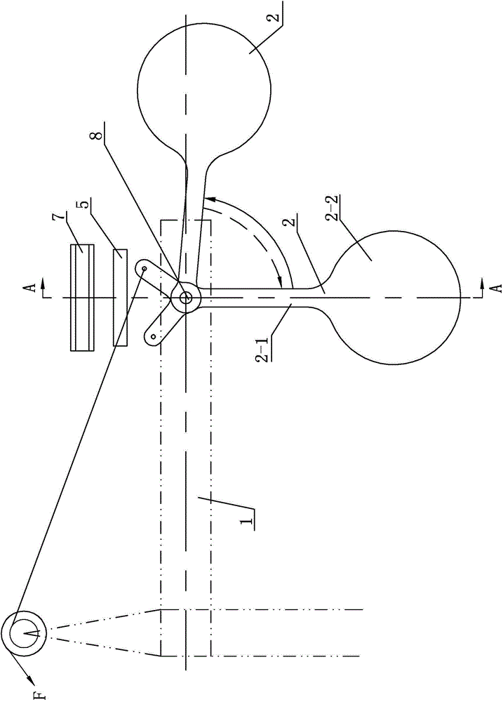
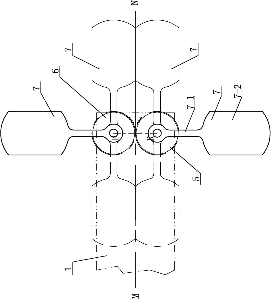
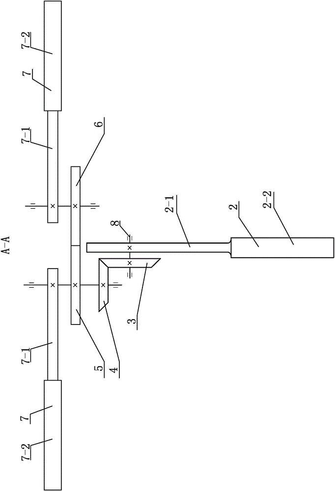
[0010] Specific implementation mode one: combine Figure 1-Figure 3 To illustrate this embodiment, a horizontally rotating movable counterweight mechanism in this embodiment includes a second counterweight 2, a first bevel gear 3, a second bevel gear 4, a first spur gear 5, a second spur gear 6 and Two first counterweights 7, the second counterweight 2 are installed on the balance arm 1 below the middle part of the connecting straight line PR of the two first counterweights 7 rotation centers, the second counterweight 2 can be positioned relative to the balance arm 1 Swing in the vertical plane, the second counterweight 2 swings in an angle range of 0° to 90°, the second counterweight 2 is connected with the force-bearing member of the tower crane that responds to the lifting moment, and the gear shaft of the first bevel gear 3 is installed with The second counterweight 2, the axial direction of the first bevel gear 3 is perpendicular to the vertical direction, the first bevel...

specific Embodiment approach 2

[0014] Specific implementation mode two: combination figure 1 and image 3 This embodiment is described. The second counterweight 2 in this embodiment is connected to the balance arm 1 through the horizontal shaft 8 provided on the balance arm 1. Swing in the vertical plane, the gear shaft of the first bevel gear 3 is connected with the horizontal rotating shaft 8 . With such arrangement, the connection is reliable and convenient, and the transmission is convenient. Others are the same as in the first embodiment.

specific Embodiment approach 3

[0015] Specific implementation mode three: combination Figure 1-Figure 3 To describe this embodiment, the transmission ratio between the second bevel gear 4 and the first bevel gear 3 in this embodiment is 2:1. Such setting can well satisfy the actual transmission of the second counterweight and the two first counterweights. When the second counterweight rotates at an angle of 90 degrees, the two first counterweights rotate at an angle of 180 degrees to achieve reclining Optimum balance of moment and forward tilt moment.


PUM


Abstract

The invention provides a horizontal rotation type movable counter weight mechanism, relates to a movable counter weight mechanism, and solves the problems of an existing movable counter weight that the load moment balancing effect on a tower crane is poor and the adaptability is poor. The horizontal rotation type movable counter weight mechanism comprises a second counter weight, a first bevel gear, a second bevel gear, a first straight gear, a second straight gear and two first counter weights, wherein the second counter weight can swing in a vertical plane relative to a balancing arm; the second counter weight is connected with a stressed component of a tower crane reaction hoisting moment; a gear shaft of the first bevel gear is provided with the second counter weight; the axial direction of the first bevel gear is vertical to the vertical direction; the first bevel gear is engaged with the second bevel gear; the second bevel gear and the first straight gear are coaxially arranged; the first straight gear is engaged with the second straight gear; each of the gear shafts of the first straight gear and the second straight gear is provided with one first counter weight. The horizontal rotation type movable counter weight mechanism provided by the invention is used for balancing the load moment of the tower crane.

Description

technical field [0001] The invention relates to a mobile counterweight mechanism, in particular to a horizontally rotating mobile counterweight mechanism. Background technique [0002] Tower crane, also known as tower crane, is a kind of lifting equipment used in construction. The tower crane needs a basic part when it is installed on the ground; the tower body is the body of the tower body, which is also a raised part; The tower crane can be raised; the slewing is to keep the upper body of the tower crane to rotate horizontally; the hoisting mechanism is used to lift the heavy object; the balance jib is to maintain the balance of the moment; part; the trolley is used to install pulley blocks, steel ropes and hooks, and it is also the part that is directly stressed; the top of the tower is of course used to maintain the force balance of the jib; the cab is the place for operation; the luffing is to make the trolley along the track In progress. [0003] The mobile counterwe...

Claims


Application Information

Patent Timeline
Patent Type & Authority Patents(China)
IPC IPC(8): B66C23/76
Inventor 兰朋刘曼兰
Owner HARBIN INST OF TECH
Why Eureka
Try Eureka