Compensated drainage floor drain

A compensating, floor drain technology, which is applied in water supply installations, indoor sanitary plumbing installations, buildings, etc., can solve the problems of increased floor drain installation height, slow floor drain drainage speed, and increased difficulty in floor drain installation, achieving increased and reduced drainage speeds The effect of reducing the depth and installation height

Active Publication Date: 2013-11-27
NINGBO HIGH NEW HAIZI TOLIET & BATHROOM PROD CO LTD
View PDF4 Cites 3 Cited by
  • Summary
  • Abstract
  • Description
  • Claims
  • Application Information

AI Technical Summary

Problems solved by technology

Therefore, in the case that no water is injected into the floor drain, increasing the depth of the water seal pipe in order to prolong the time of the water seal at room temperature will increase the installation height of th

Method used


Image

  • Compensated drainage floor drain
  • Compensated drainage floor drain
  • Compensated drainage floor drain

Examples


Embodiment

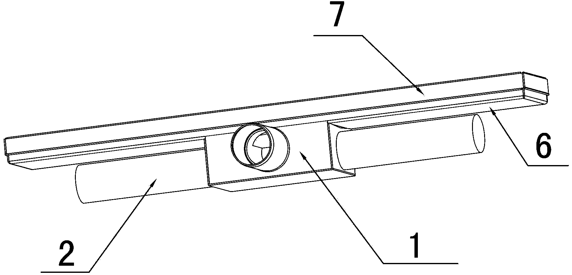
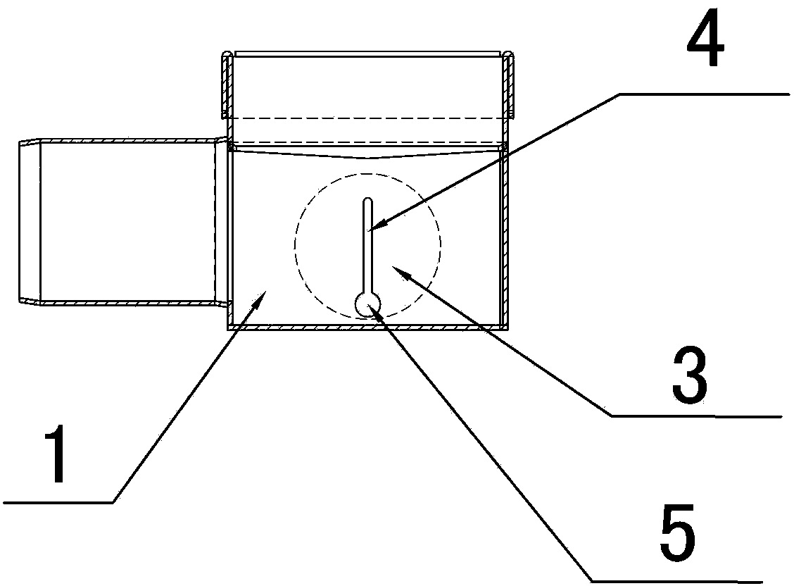
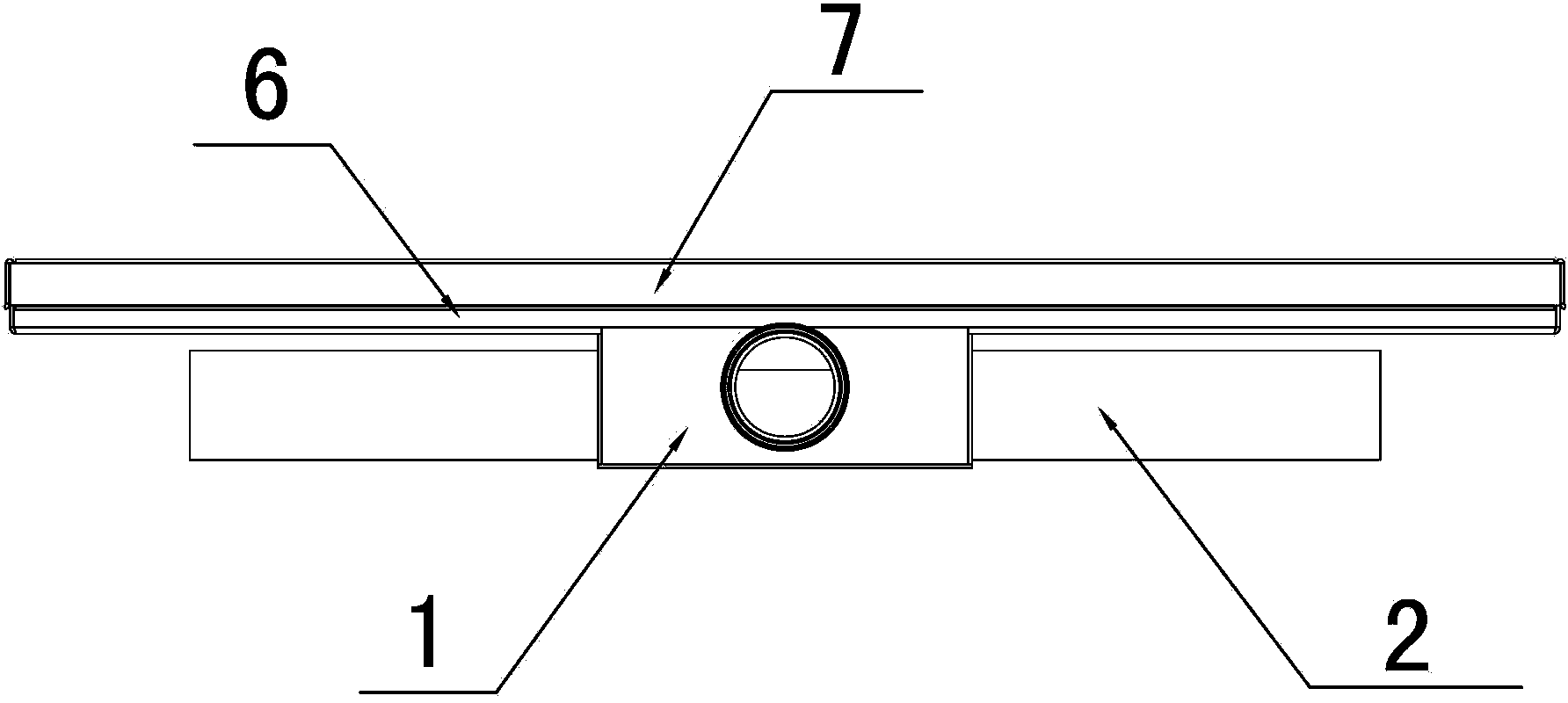
[0020] Embodiment: As shown in the figure, a compensated drainage floor drain includes a water tank 1 and an outlet pipe 2. The water tank 1 has a front side 3 and two side surfaces 4. The water outlet pipe 2 is arranged on the front side 3. A water diversion tank 5 is extended, and at least one water storage pipe 6 for replenishing water to the water tank 1 is provided. The water storage pipe 6 is arranged on the two sides 4 and communicates with the water tank 1 through a narrow water replenishment seam 7. The water storage pipe 6 is far away from the One end of the water tank 1 is a closed end 7, and the water storage pipe 6 is located directly below the water diversion tank 5, and the closed end 8 does not extend beyond the end of the water diversion tank 5. When the water evaporation in the water tank 1 decreases, the water in the water storage pipe 6 Water is just replenished in the middle of the tank 1 by the water filling seam 7 .

[0021] In this embodiment, the botto...


PUM


Abstract

The invention discloses a compensated drainage floor drain. The compensated drainage floor drain comprises a water tank and a water outlet pipe, wherein the water tank is provided with a front side surface and two side surfaces; the water outlet pipe is arranged on the front side surface; gutters are arranged on two sides of the upper end of the water tank in an extending manner; the compensated drainage floor drain further comprises at least one water storage pipe used for replenishing water for the water tank, arranged on the two side surfaces and communicated with the water tank through narrow water replenishing seams; the ends of the water storage pipes, far away from the water tank, are closed ends; the water storage pipes are positioned right below the gutters, and the closed ends do not extend beyond the end parts of the gutters; when water in the water tank is evaporated and reduced, water in the water storage pipes flows into the water tank through the water replenishing seams. The compensated drainage floor drain has the advantages of low installation height, high drainage speed and long water-sealing stink-proof time.

Description

technical field [0001] The invention relates to a drainage and odor-proof floor drain, in particular to a compensation type drainage floor drain. Background technique [0002] At present, floor drains are basically installed in house construction for drainage. The existing drainage floor drain includes a water tank, a water sealing device and a water outlet pipe. The water sealing device is located in the water tank, and the water outlet pipe is installed on the side of the water tank and communicates with the water outlet of the water sealing device. When draining, the water enters the water seal device from the water tank, and then is discharged from the water seal device through the outlet pipe. The water in the water seal device seals the outlet pipe. In the case of no water injected into the floor drain, the water in the tank can evaporate naturally. - For 4 working days, before the water evaporates naturally, the odor cannot enter the floor drain from the outlet pipe ...

Claims


Application Information

Patent Timeline
IPC IPC(8): E03C1/28
Inventor 周赐平
Owner NINGBO HIGH NEW HAIZI TOLIET & BATHROOM PROD CO LTD
Why Eureka
Try Eureka