
A Method for Adaptive Geometric Correction of Projector Picture

A technology of geometric correction and projector, which is applied in the direction of image reproducer of projection device, instrument, and parts of color TV, etc., can solve the problems of high synchronization requirements of camera parameters and difficult hardware to achieve accuracy.

Active Publication Date: 2016-12-28
ZHEJIANG UNIV
View PDF7 Cites 1 Cited by
  • Summary
  • Abstract
  • Description
  • Claims
  • Application Information

AI Technical Summary

Problems solved by technology

Later, a method of light and dark differential projection was developed according to the specificity of human vision. Due to the compensation of the human eye for light and dark patterns, the existence of coding cannot be felt, but the camera can capture these light and dark coding information with the help of a certain sampling frequency. , the specific method is to perform differential superposition on the projected image according to the coding to generate two images, one image is positive superposition coding, and the other is negative superposition coding, project these two frames at a specific frequency, and then carry out synchronous calibration of the camera, This method has high requirements on the synchronization of the frame rate of the camera and the frequency of the projector. It is difficult for general hardware to achieve such accuracy, and when the human eye observes the projected screen when it is moving, it can detect the difference between the two images.

Method used


Image

  • A Method for Adaptive Geometric Correction of Projector Picture
  • A Method for Adaptive Geometric Correction of Projector Picture
  • A Method for Adaptive Geometric Correction of Projector Picture

Examples


Embodiment Construction

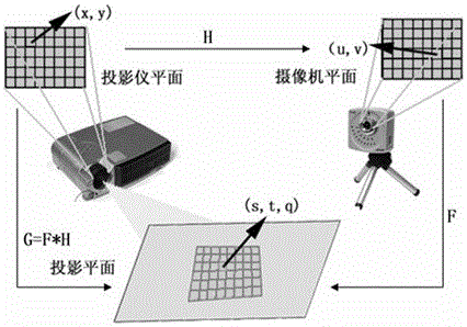
[0024] The method for adaptive geometric correction of the projector screen according to the present invention will be further described below in conjunction with the accompanying drawings. Image 6 is a flow chart of adaptive geometric correction of the projector screen, such as Image 6 As shown, the method for adaptive geometric correction of the projector picture of the present invention comprises the following steps:

[0025] Step 1) Before the projector is started, use the camera to face the projection plane and take at least one frame of the projection plane image without the projection picture in advance.

[0026] Step 2) Extract a frame of uncorrected target original image from the image library, and the projector directly projects the target original image onto the projection plane to obtain the current projection image.

[0027] Step 3) The camera shoots the projection plane image of the current projection picture; the point cloud sample data of the projection plan...


PUM


Abstract

The invention discloses a method for self-adaptation geometric correction of a projector picture. The method for self-adaptation geometric correction of the projector picture comprises the steps of (1) shooting a projection plane image without a projection picture, (2) projecting a target original image to be corrected on a projection plane to obtain a current projection picture, (3) shooting a projection plane image of the current projection picture, (4) collecting point cloud sample data of the projection plane, (5) obtaining a homography matrix from a camera plane to the projection plane, (6) identifying a frame number which corresponds to the current projection picture, searching for an original projection image corresponding to the current projection picture, (7) obtaining the corresponding relation, between the projection plane image of the currently existing projection picture and the original projection image of the currently existing projection picture about two-dimensional position coordinates with the matching characteristics, obtaining a homography matrix from the projector plane to the camera plane, obtaining a homography matrix from the projector plane to the projection plane, (8) carrying out scale variation processing on a target original image, to be corrected, of a next frame to generate a variation projection image, and (9) projecting the variation projection image on the projection plane to obtain a new current projection picture.

Description

technical field [0001] The invention relates to a method for adaptive geometric correction of a projector picture, and belongs to the technical field of projector picture correction. Background technique [0002] The adaptive geometric correction of the projector screen is to automatically correct the projector screen according to the specific type of surface information. In 2005, Bimber proposed to map the two-dimensional P2C texture to the original image. This texture is also called communication texture. It contains the coordinates of each pixel in the image and assigns a specific floating point color value. Then The three-dimensional information of the projection surface is calculated by detecting the pixel-level displacement of its texture after projection. This simple embedding method based on image content often relies excessively on the information of the image itself, and does not accurately match the three-dimensional information of the projection surface. It is e...

Claims


Application Information

Patent Timeline
Patent Type & Authority Patents(China)
IPC IPC(8): H04N5/74H04N9/31G06T5/00
Inventor 王锐华炜鲍虎军许庶
Owner ZHEJIANG UNIV
Learn More