Seal ring

一种密封环、凹部的技术,应用在发动机的密封、机械设备、发动机元件等方向,能够解决油泄漏等问题,达到低泄漏、降低摩擦力、抑制泄漏的效果

Inactive Publication Date: 2013-11-27
RIKEN CO LTD
View PDF11 Cites 13 Cited by
  • Summary
  • Abstract
  • Description
  • Claims
  • Application Information

AI Technical Summary

Problems solved by technology

[0007] In the seal ring of Patent Document 1, the sliding contact between the side surface of the seal ring and the ring groove is line contact, and the sliding path is located on the joint gap of the seal ring, so there is a problem of oil leakage from the joint gap.

Method used


Image

  • Seal ring
  • Seal ring
  • Seal ring

Examples


Embodiment 1)

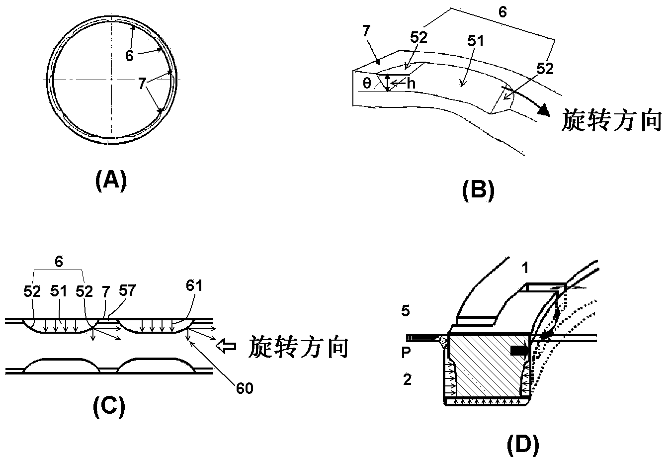
[0043] Using PEEK material with carbon fiber added, through injection molding, a image 3 (A) The seal ring of the recessed part shape of the structure shown. Here, when the curvature of the throttle portion is R40, eight recesses with a depth of 0.22 mm and a circumferential width of 24 mm are formed on the contact side surface and the pressure receiving side surface, respectively. The outer diameter (nominal diameter) of the sealing ring is 67mm, the thickness (radial width) is 2.3mm, the width (axial width) is 2.32mm, and the interface is Figure 5 Three step openings shown. In addition, when the axial width of the seal ring is 100, the depth of the deepest part is 9.5; when the circumferential length of one recess is 100, the circumferential width of the deepest part is 16.9; When the sum is 100, the sag length of the R-curved surface of the throttle portion is 13.9, and the depth of the throttle portion is 15.0 when the depth of the deepest portion of the concave portio...

Embodiment 2~5)

[0053] In the same manner as in Example 1, a PEEK material with carbon fiber added was used by injection molding to manufacture a image 3 (A) The seal ring of the recessed part shape of the structure shown. Here, the curvature of the throttle portion was changed so that the depth h of the deepest portion was 0.03 mm (Example 2), 0.08 mm (Example 3), 0.12 mm (Example 4), and 0.41 mm (Example 5), respectively. . In addition, the outer diameter (nominal diameter) of the sealing ring is 67mm, the thickness (radial width) is 2.3mm, the width (axial width) is 2.32mm, and the interface is Figure 5 Three step openings shown. When the axial width of the seal ring is 100, the depths of the deepest portions of the respective examples are 1.3 (Example 2), 3.4 (Example 3), 5.2 (Example 4), and 17.7 (Example 5). The frictional force and oil leakage amount of the obtained seal ring were measured in the same manner as in Example 1.

[0054] Figure 7 In the graph, the results (·) of th...

Embodiment 6~10)

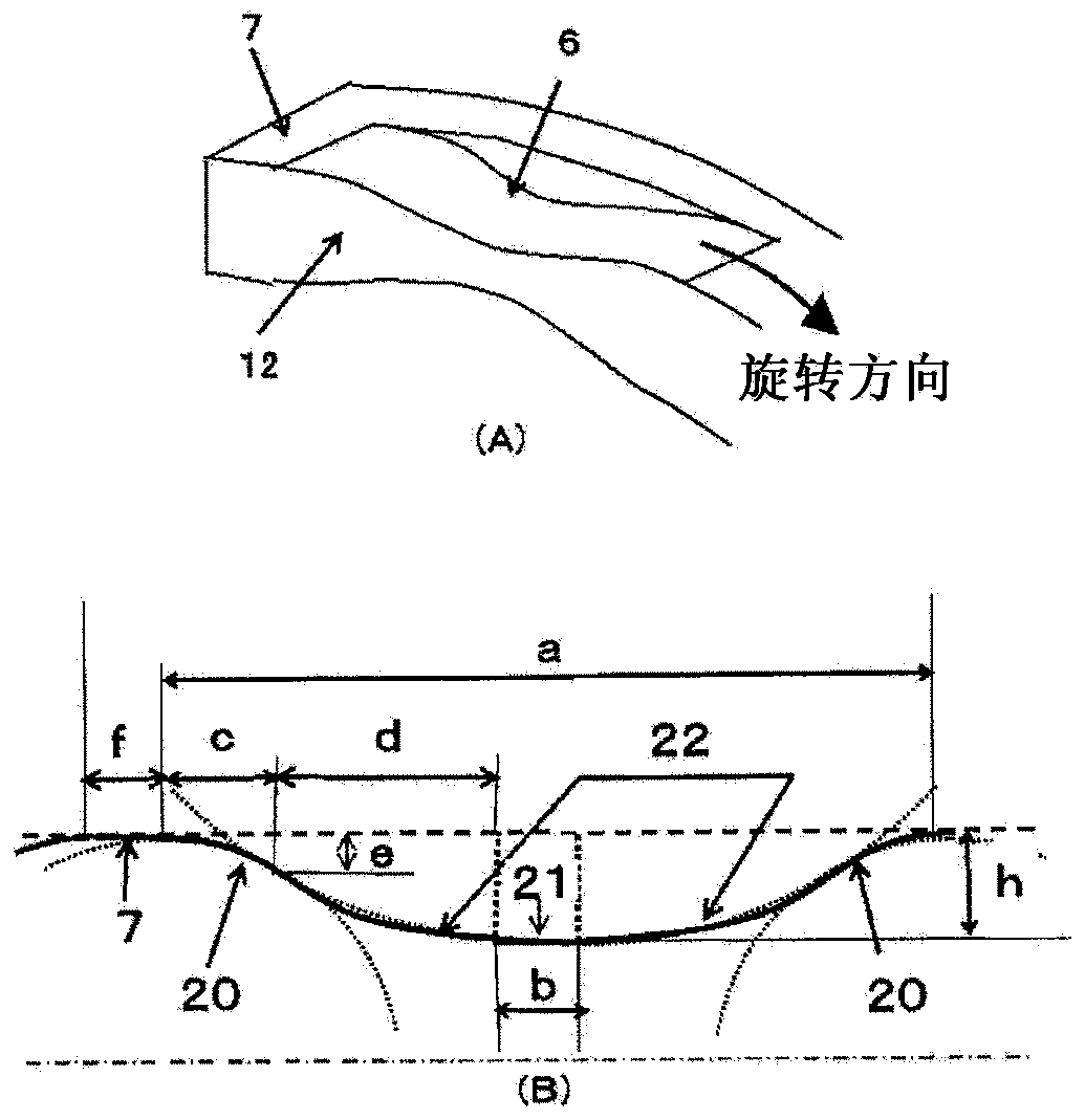
[0058] Using PEEK material with carbon fiber added, through injection molding, a Figure 4(A) The seal ring of the recessed part shape of the structure shown. An inner wall with a width of 0.3 mm and a circumferential length of 10 mm on one side was provided along the inner peripheral end from both ends of the recesses toward the center, and an oil introduction hole with a circumferential length of 4 mm was formed in the center. Here, the curvature of the throttling portion was changed, and the deepest portions h were manufactured to be 0.03 mm (Example 6), 0.08 mm (Example 7), 0.12 mm (Example 8), and 0.22 mm (Example 9). ), and a sealing ring of 0.41 mm (Example 10). In addition, the outer diameter (nominal diameter) of the sealing ring is 67mm, the thickness (radial width) is 2.3mm, the width (axial width) is 2.32mm, and the interface is Figure 5 Three step openings shown. The frictional force and oil leakage amount of each seal ring were measured in the same manner as ...


PUM


Abstract

[Problem] To provide a seal ring having both low-friction characteristics and low-leakage characteristics, that improves drive loss in an automatic transmission, and that is capable of contributing to improved fuel consumption in an automobile. [Solution] A plurality of recessed sections, which are separated in the peripheral direction of a shaft via pillar sections, are formed in a seal ring, which is mounted to a shaft groove formed in the outer peripheral surface of the shaft, in at least the inner peripheral side of the seal ring side surface in contact with the shaft groove. End sections on both sides of the recessed sections in the peripheral direction are configured by an aperture section comprising a curved surface protruding towards the pillar section. In addition, the depth (h) of the deepest section having the greatest width in the shaft direction of the recessed sections is set in a range of 2-17, when the width in the shaft direction of the seal ring is 100.

Description

technical field [0001] The invention relates to a sealing ring, in particular to a sealing ring used in hydraulic equipment such as automatic transmissions of automobiles. Background technique [0002] In recent years, in order to improve the fuel economy of automobiles, it is required to reduce the driving loss of the automatic transmission. A seal ring is installed in an automatic transmission for the purpose of a hydraulic seal, but the loss of frictional force of the seal ring causes a drive loss of the automatic transmission. Therefore, reducing the frictional force of the seal ring has become an important issue. In addition, since the capacity of the oil pump of the automatic transmission accounts for a large proportion of the drive loss, it is desired to reduce the amount of oil leakage from the seal ring and to reduce the capacity of the oil pump. In this way, in order to reduce the driving loss of the automatic transmission and improve the fuel economy of the auto...

Claims


Application Information

Patent Timeline
Patent Type & Authority Applications(China)
IPC IPC(8): F16J15/18F16J15/46
CPCF16J15/18F16J15/3448F16J15/441F16J15/164F16J15/3272
Inventor 永井纯也齐藤美香柴野知哉
Owner RIKEN CO LTD
Why Eureka
Try Eureka