Bridge type concentric constant pressure water distributor

A water distributor and bridge-type technology, which is applied in the direction of production fluid, wellbore/well components, earthwork drilling and production, etc., can solve the problems such as the decline in the qualification rate of layered water injection, the inability to automatically adjust for a long time, and the restriction of the effect of layered water injection. Overcoming layered flow changes, excellent layered water injection effect, and improved flow control effect

Pending Publication Date: 2018-11-30
PETROCHINA CO LTD
View PDF0 Cites 4 Cited by
  • Summary
  • Abstract
  • Description
  • Claims
  • Application Information

AI Technical Summary

Problems solved by technology

[0003] The purpose of the present invention is to overcome the shortcomings of the above-mentioned prior art, and provide a bridge-type concentric constant pressure water distributor, which overcomes 1 in the prior art: the bridge-type concentric dispensing process in the early stage can only be manually tested and adjusted for a short time,

Method used


Image

  • Bridge type concentric constant pressure water distributor
  • Bridge type concentric constant pressure water distributor

Examples


specific Embodiment approach

[0021] It should be noted that the structures, proportions, sizes, etc. shown in the drawings attached to this specification are only used to match the content disclosed in the specification, for those who are familiar with this technology to understand and read, and are not used to limit the implementation of the present invention Any modification of the structure, change of the proportional relationship or adjustment of the size shall still fall within the scope of the technical content disclosed in the present invention without affecting the effect and purpose of the present invention. In the range.

[0022] At the same time, terms such as "upper", "lower", "left", "right", "middle" and "one" quoted in this specification are only for the convenience of description and are not used to limit this specification. The practicable scope of the invention and the change or adjustment of its relative relationship shall also be regarded as the practicable scope of the present inventi...

Embodiment 1

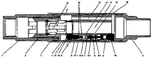
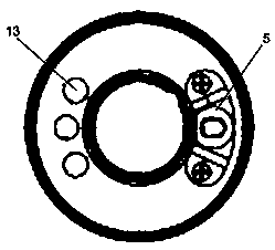
[0024] Such as Figure 1~2 As shown, the present invention discloses a bridge-type concentric constant pressure water distributor, including an upper joint 1, a positioning platform 2, a concentric adjustment sleeve 3, an outer casing 4, an adjustment mechanism 5, a main structure 16 and a lower joint 11. One end of the upper joint 1 is connected to the outer casing 4, wherein the other end of the outer casing 4 is connected to the main structure 16, and the other end of the main structure 16 is connected to the lower joint 11, and one end of the positioning platform 2 is set inside the upper joint 1, wherein The other end of the positioning platform 2 is connected to the main structure 16, one end of the concentric adjustment sleeve 3 is set inside the positioning platform 2, and the other end of the concentric adjustment sleeve 3 is connected to the main structure 16, the upper joint 1, the positioning platform 2, the concentric The adjustment sleeve 3, the outer casing 4, t...

Embodiment 2

[0026] Such as Figure 1~2 As shown, the present invention discloses a bridge-type concentric constant pressure water distributor, including an upper joint 1, a positioning platform 2, a concentric adjustment sleeve 3, an outer casing 4, an adjustment mechanism 5, a main structure 16 and a lower joint 11. One end of the upper joint 1 is connected to the outer casing 4, wherein the other end of the outer casing 4 is connected to the main structure 16, and the other end of the main structure 16 is connected to the lower joint 11, and one end of the positioning platform 2 is set inside the upper joint 1, wherein The other end of the positioning platform 2 is connected to the main structure 16, one end of the concentric adjustment sleeve 3 is set inside the positioning platform 2, and the other end of the concentric adjustment sleeve 3 is connected to the main structure 16, the upper joint 1, the positioning platform 2, the concentric The adjustment sleeve 3, the outer casing 4, t...


PUM


Abstract

The invention discloses a bridge type concentric constant pressure water distributor. The bridge type concentric constant pressure water distributor comprises an upper joint, a positioning platform, aconcentric adjusting sleeve, an outer protective casing, an adjusting mechanism, a main structure and a lower joint. The outer protective casing is connected to one end of the upper joint, the main structure is connected to the other end of the outer protective casing, and the lower joint is connected to the other end of the main structure. One end of the positioning platform is installed insidethe upper joint in a sleeved mode, and the main structure is connected to the other end of the positioning platform. One end of the concentric adjusting sleeve is installed inside the positioning platform in a sleeved mode, and the main structure is connected to the other end of the concentric adjusting sleeve. The upper joint, the positioning platform, the concentric adjusting sleeve, the outer protective casing, the main structure and the lower joint are centrally penetrated and coaxially arranged, the adjusting mechanism is installed and pressed tightly between the main structure and the outer protective casing in a sleeved mode, and the concentric adjusting sleeve meshes with one end of the adjusting mechanism. The design combining electric direct adjustment of downhole flow and a constant pressure control technology is adopted in the bridge type concentric constant pressure water distributor, the flow control effect is improved, and the voltage stabilization and constant voltage control are realized.

Description

technical field [0001] The invention belongs to the technical field of oilfield water injection, in particular to a bridge-type concentric constant-pressure water distributor. Background technique [0002] The bridge-type concentric layered water injection technology is another high-efficiency separate injection technology after the bridge-type eccentric separate injection technology. It has many separate injection stages, adapts to large well deviation, produced water, small water volume and other separate injection conditions, which greatly meets the requirements The demand for fine injection in oilfields; in recent years, domestic water injection development oilfields have focused on the promotion and application of this technology, and achieved good results in water injection development. As the core tool of this technology, the bridge-type concentric water distributor adopts concentric docking and concentric adjustment, which has the advantages of high docking success r...

Claims


Application Information

Patent Timeline
IPC IPC(8): E21B43/20
CPCE21B43/20
Inventor 杨玲智姚斌于九政徐自强姬振宁胡改星毕福伟王子建刘延青
Owner PETROCHINA CO LTD
Why Eureka
Try Eureka