Flow control of an injection molding system

a flow control and injection molding technology, applied in the direction of fluid pressure control, process and machine control, instruments, etc., can solve the problems of inhomogeneity in the structure of molded parts, difficulty in completely filling the cavity of molding tools with melt, and already clear reduction of temperature. , to achieve the effect of better control of the adjustable flow control valve and higher accuracy

Active Publication Date: 2020-12-24
INCOE CORP
View PDF0 Cites 0 Cited by
  • Summary
  • Abstract
  • Description
  • Claims
  • Application Information

AI Technical Summary

Benefits of technology

[0042]With the help of the flow sensors a better control of the adjustable flow control valves can be achieved. Due to the actual measured flow amount in the pressure lines the status of the actuator system can be determined with a higher accuracy and the timing and the timing preciseness of the control of the adjustable flow control valve and thus the needle during the injection phase or other actuator systems can be improved.

Problems solved by technology

In the injection molding of flat and / or elongated parts through a single ingate (feed orifice) it is difficult to fill the cavity of the molding tool completely with melt.
Furthermore, when areas of the cavity which are distant from the feed orifice are reached by the melt, its temperature is already clearly reduced, due to which inhomogeneities in the structure of the molded parts can arise.
The cascade process described so far has the disadvantage that on the opening of a second nozzle, or additional nozzles, the melt is injected at the pressure predetermined by the injection molding machine and the pressure is of equal magnitude for all the nozzles.
Since when the flow front of a previously opened nozzle arrives at the feed orifice of a neighboring nozzle the melt of that flow front has already suffered a cooling and a loss of pressure, undesirable flow front markings arise due to melt under full pressure appearing explosively at the nozzle which opens later.

Method used


Image

  • Flow control of an injection molding system
  • Flow control of an injection molding system
  • Flow control of an injection molding system

Examples


Embodiment Construction

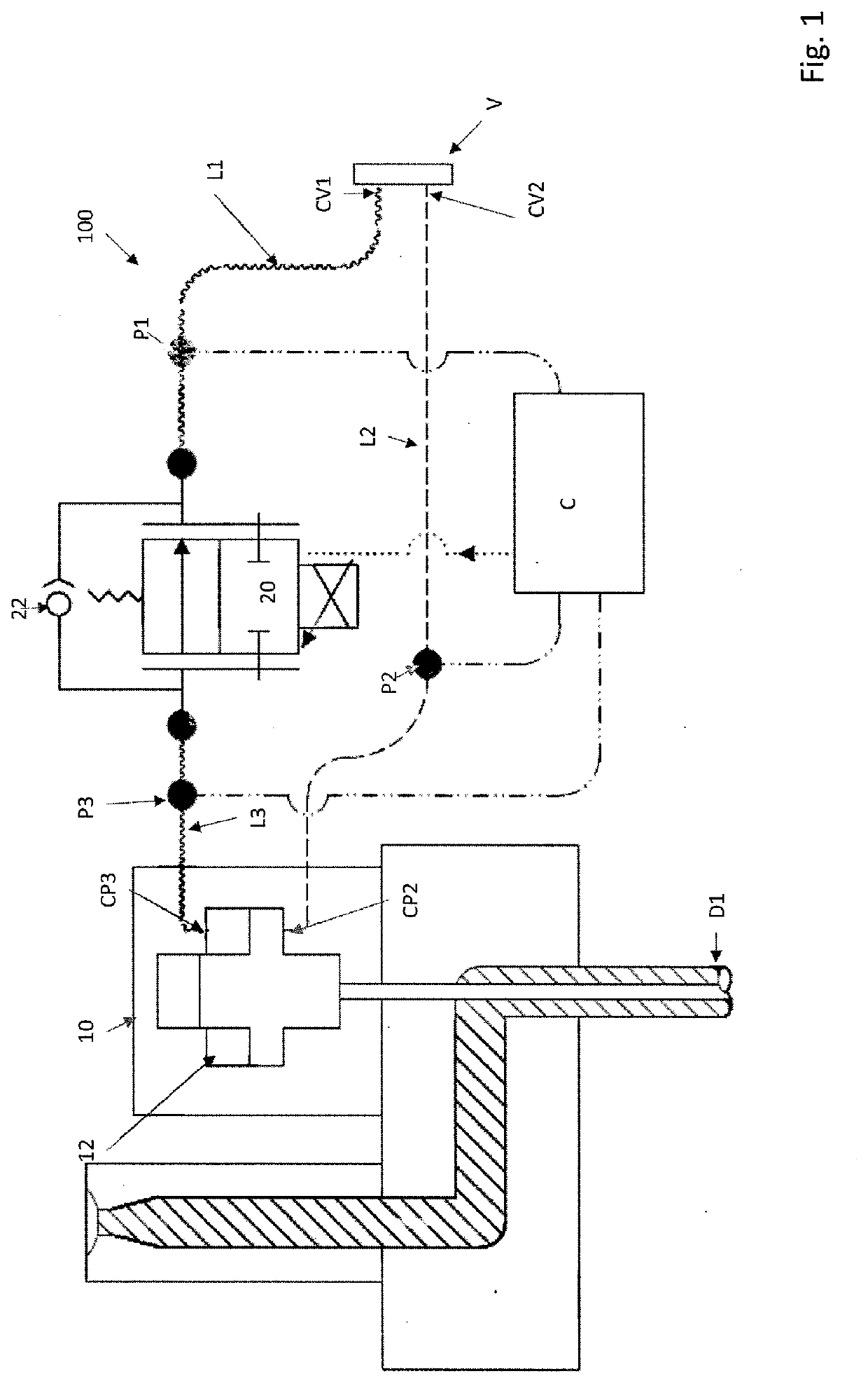
[0053]FIG. 1 shows an actuator system 100 comprising an electrically controllable flow control valve 20 which is introduced between the pressure line L1 and L3, which is connected to the cylinder space 12 of the piston drive 10 via which a nozzle is closed when pressurizing medium is fed to the cylinder space 12. The flow control valve 20 consists of an adjustable throttle valve and, lying parallel thereto, a check valve 22 whose direction of passage is toward the piston-cylinder drive 10. Wherein an embodiment without the check valve is possible. The controllable flow control valve prevents a sudden flow of the pressurizing medium out and / or in of the cylinder space 12, and thus a sudden opening and / or closing of the temporally downstream nozzle and thus the explosive injection of the melt 13 into the cavity, so that no flow front markings on the injected object result. In this embodiment a check valve 22 is disclosed, which can be integrated, and is consequently optional. In the s...


PUM

PropertyMeasurementUnit
pressureaaaaaaaaaa
speedaaaaaaaaaa
flow rateaaaaaaaaaa

Abstract

Injection molding system comprising at least one first actuator-system (D1, D2, D3), the first actuator system comprising: at least one piston drive having at least two pressure line connectors (CP2, CP3) to drive a piston to open or close a molding nozzle, pressure lines (L1, L2) connectable to a changeover valve (V) having a pressure line connector (P) and tank line connector (T) and at least two changeover pressure line connectors, wherein the first changeover valve pressure line connector (CV1) is connectable to a first pressure line (L1) and the second changeover valve pressure line connector (CV2) is connectable to a second pressure line (L2), wherein the second pressure line (L2) is connected to the second pressure line connector (CP2) of the piston drive, an electronically adjustable flow control valve having a first pressure line connector and a second pressure line connector, wherein the first pressure line connector of the adjustable flow control valve being connected to the first pressure line (L1) to allow a connection to the first pressure line connector (CV1) of the changeover valve (V), and the second pressure line connector is connected to a third pressure line (L3) which establishes a connection to the second pressure line connector (CP3) of the piston drive, at least one electronic flow sensor for (P1, P2, P3) sensing flow rate in the first, second and/or third pressure lines (L1, L2, L3), a controller connected to the adjustable flow control valve and to the at least one sensor, configured to electronically adjust the flow control valve, depending on information of the at least one sensor, controlling thereby the timing and the speed of the movement of the piston and the molding nozzle.

Description

CROSS-REFERENCE TO RELATED APPLICATIONS[0001]Not Applicable.FIELD OF THE DISCLOSURE[0002]The present invention relates to a process and device for injection molding, in particular to a cascade injection molding process.BACKGROUND OF THE DISCLOSURE[0003]In the injection molding of flat and / or elongated parts through a single ingate (feed orifice) it is difficult to fill the cavity of the molding tool completely with melt. Furthermore, when areas of the cavity which are distant from the feed orifice are reached by the melt, its temperature is already clearly reduced, due to which inhomogeneities in the structure of the molded parts can arise.[0004]For this reason, it is a known practice, particularly in the case of the molding of elongated and / or flat parts, to fill the cavity of the molding tool with melt through several feed orifices. In connection with this, flow lines result from the melt flow fronts issuing from the feed orifices meeting one another somewhere between neighboring ...

Claims


Application Information

Patent Timeline
Patent Type & Authority Applications(United States)
IPC IPC(8): B29C45/30F16K21/18F16K1/52
CPCB29C45/30F16K1/52F16K21/185B29C2045/2824B29C45/2803B29C45/281B29C45/2703B29C45/2708B29C45/7613B29C2045/2709B29C2045/7606B29C2045/2817B29C2045/0032B29C45/82B29C2945/76056B29C2945/7606B29C2945/76381B29C2945/76538B29C2945/76307B29C2945/76785B29C2945/76859B29C2945/76933B29C2945/76943G05D16/2097B29C45/77B29C45/766B29C45/7666
Inventor JORG, ANTONGREB, SCOTTSTRIEGEL, CHRISTIAN
Owner INCOE CORP
Why Eureka
Try Eureka