Push liquid pump
A liquid pump, push-type technology, applied in the field of liquid pumps, can solve the problems of metal springs that are not easy to disassemble, lack of resilience, and feel heavy when pressed, so as to avoid external collision damage, improve aesthetics, delay creep and The effect of fatigue failure
- Summary
- Abstract
- Description
- Claims
- Application Information
AI Technical Summary
Problems solved by technology
Method used
Image
Examples
no. 1 example
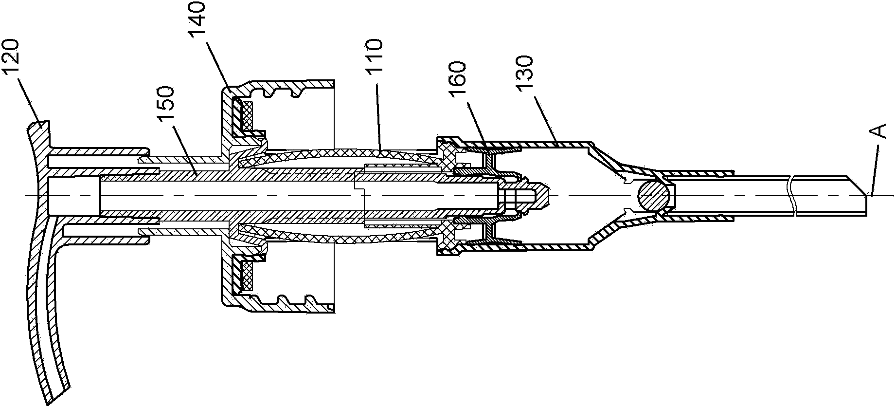
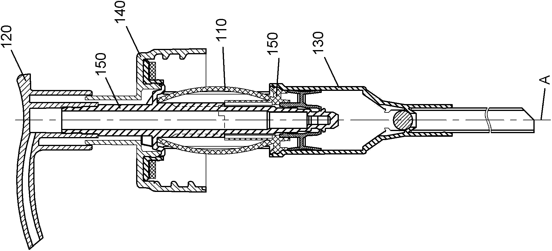
[0073] see figure 1 -7, which shows the push-type liquid pump of the first embodiment of the present invention. The push-type liquid pump is used to be mounted on a container (not shown) to pump the liquid product inside the container to the outside of the container. Generally speaking, the liquid pump includes a fixed unit that remains fixed relative to the container and a movable unit that can reciprocate relative to the fixed unit, and the liquid product is pumped to the outside of the container through the reciprocating motion. The reciprocating motion is applied by the user on the movable unit to move the movable unit relative to the fixed unit along the longitudinal axis A of the liquid pump and is used to move the movable unit relative to the fixed unit along the longitudinal axis A after the pressing force is removed. The elastic forces of the reset elastic reset device are coordinated to realize. In this embodiment, the fixed unit includes a mouthpiece 140 for fixi...
no. 2 example
[0087] see below Figure 8 -12, which shows the push-type liquid pump of the second embodiment of the present invention. The general structure of the push-type liquid pump is basically the same as that of the first embodiment. Specifically, the liquid pump generally includes a plastic elastic compression device 210 , a pressure head 220 , a cylinder 230 , a mouthpiece 240 , a piston rod 250 and other components.
[0088] Different from the first embodiment, the lower end of the elastic compression device 210 includes a base 212 connecting the lower end of the elastic strip 211 in the form of a ring supporting a lug 234 formed on the lower periphery of the cylinder 230 superior. In this case, a separate cylinder plug 235 formed with a central through hole through which the piston rod 250 passes is required to seal the opening portion of the cylinder.
[0089] As shown in FIG. 12 , the upper part of the cylinder 230 is formed with hollowed out portions 232 diametrically oppos...
no. 3 example
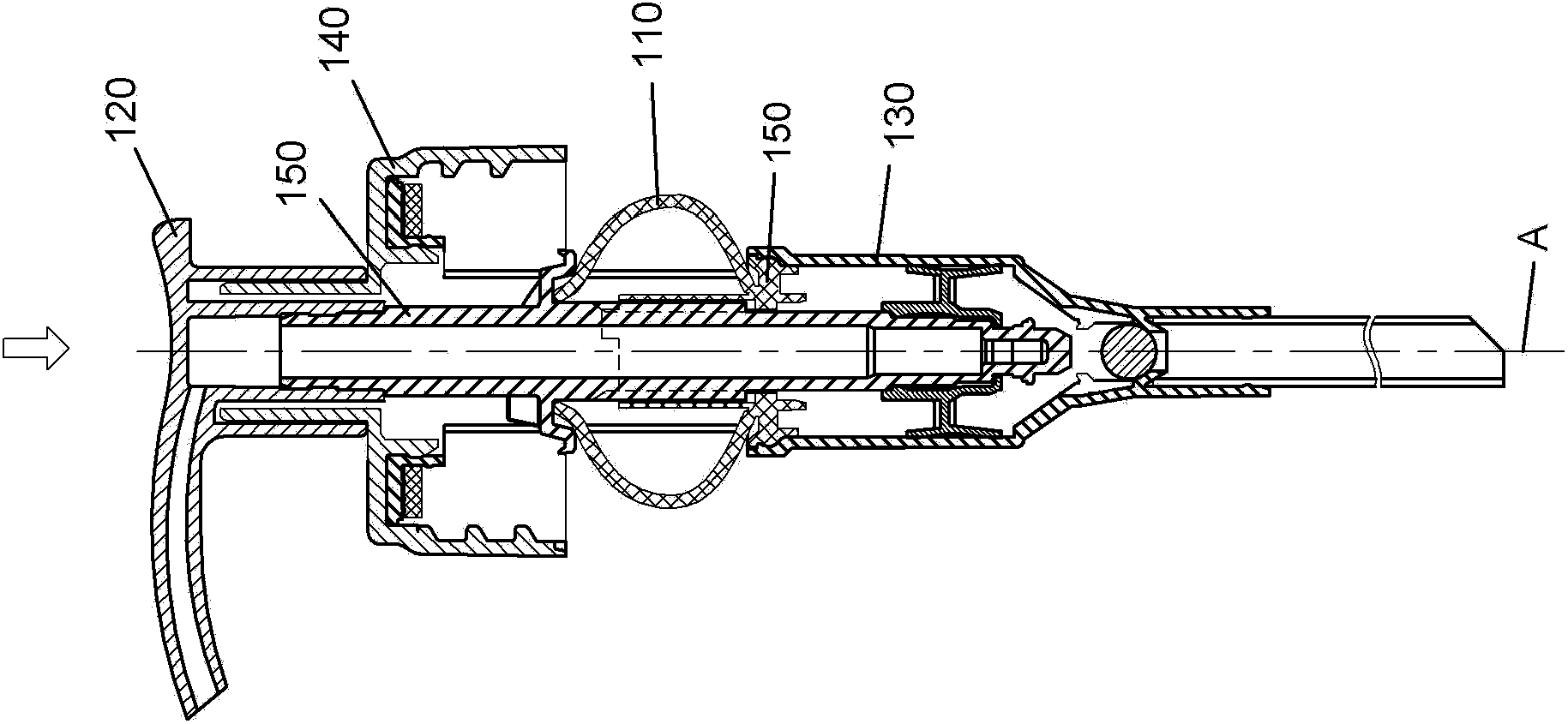
[0092] see below Figure 13 -18, which shows the push-type liquid pump of the third embodiment of the present invention. The liquid pump generally includes a plastic elastic compression device 310 , a pressure head 320 , a bellows cylinder 330 , a mouthpiece 340 , a cylinder support 345 and other components. In the liquid pump, the movable unit includes a pressure head 320, and the fixed unit includes a mouthpiece 340 and a cylinder bracket 345 integrally formed with the mouthpiece.
[0093] The plastic elastic compression device 310 includes two curved elastic strips 311 arranged symmetrically around the longitudinal axis A of the liquid pump and a base 312 connecting the upper ends of the two elastic strips 311 . Each elastic strip 311 is suitable for deformation in the plane where the arc is located, and the plane passes through the longitudinal axis A. Such a configuration makes the action line of the resultant force of the elastic force generated by the elastic strip 31...
PUM
 Abstract
Description
Claims
Application Information
 - R&D
- Intellectual Property
- Life Sciences
- Materials
- Tech Scout
- Unparalleled Data Quality
- Higher Quality Content
- 60% Fewer Hallucinations
Browse by: Latest US Patents, China's latest patents, Technical Efficacy Thesaurus, Application Domain, Technology Topic, Popular Technical Reports.
© 2025 PatSnap. All rights reserved.Legal|Privacy policy|Modern Slavery Act Transparency Statement|Sitemap|About US| Contact US: help@patsnap.com


