
Punching device based on membrane covering and laser positioning

A laser positioning and punching device technology, applied in the field of sheet metal processing, can solve the problems of inaccurate sheet positioning, low punching accuracy, lack of support devices, etc., to avoid external collision damage, easy operation, and avoid surface scratches Effect

Inactive Publication Date: 2015-09-23
SUZHOU JINGYU AUTOMATION TECH
View PDF6 Cites 1 Cited by
  • Summary
  • Abstract
  • Description
  • Claims
  • Application Information

AI Technical Summary

Problems solved by technology

The above-mentioned punching devices or punching machines are generally operated manually, that is, the plate is adjusted by manually adjusting the clamping device to adjust the processing position. The disadvantages are: the positioning of the plate is not accurate, and the punching accuracy is not high; and lack of support devices, the plate Easy to deform, affecting processing quality

Method used


Image

  • Punching device based on membrane covering and laser positioning
  • Punching device based on membrane covering and laser positioning

Examples


Embodiment Construction

[0011] The specific implementation manner of the present invention will be described below in conjunction with the accompanying drawings.

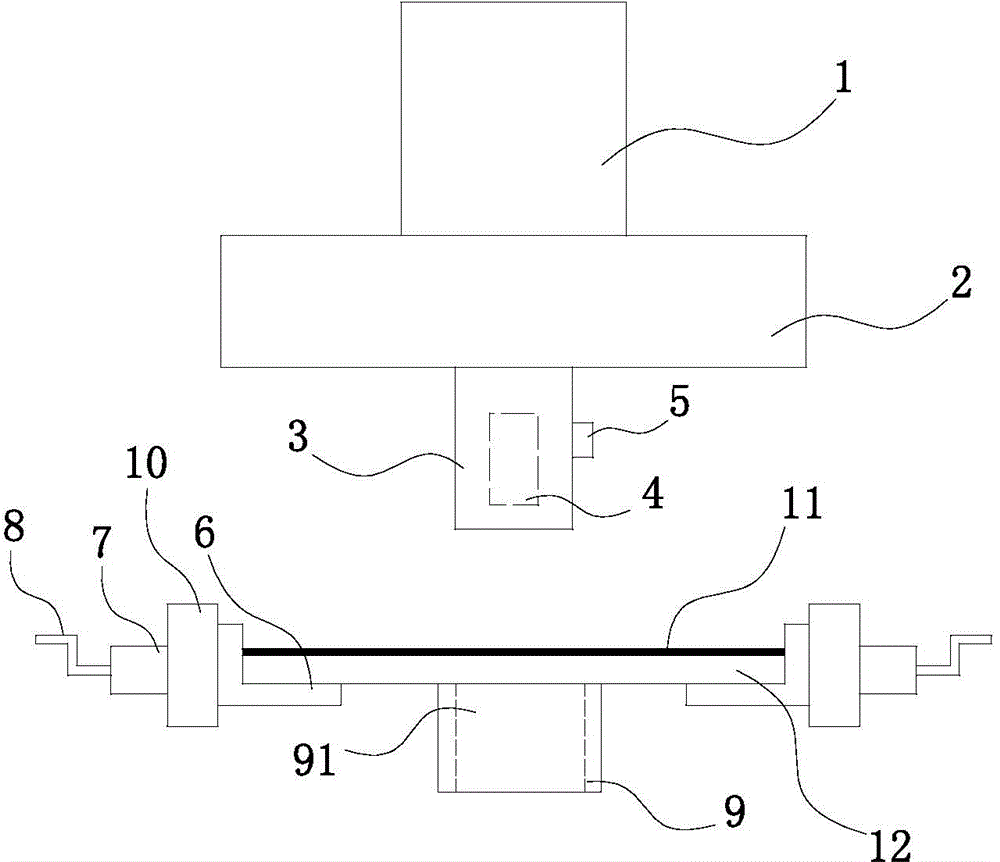
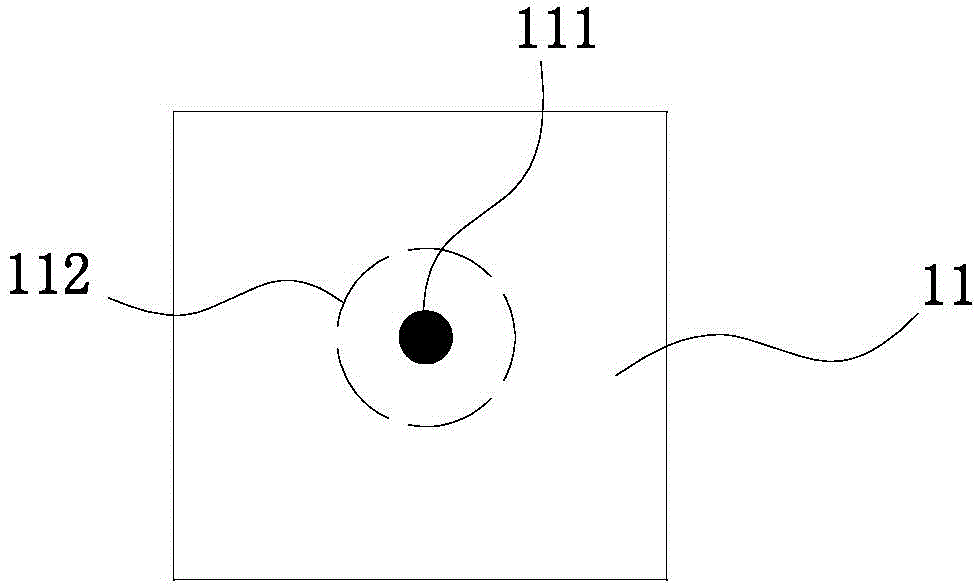
[0012] See figure 1 and figure 2 , the present invention includes a punching driving device 1, an upper template 2 and a punching head 3, and also includes a clamping device and a support block 9 positioned below the punching head 3, the clamping device includes a symmetrically arranged clamping block 6, clamping The holding block 6 is installed on the bracket 10 by means of the screw shaft 7, the outer end of the screw shaft 7 is connected to the handle 8, and the support block 9 has a punching groove 91; the laser head 4 is installed in the punching head 3 by means of the set screw 5, and the laser head The axial direction of 4 coincides with the axial direction of the punching head 3; a film 11 is attached to the upper surface of the workpiece 12, and a hole ring 112 corresponding to the processing hole is pre-cut on the film 11 and a...


PUM


Abstract

The invention relates to a punching device based on membrane covering and laser positioning. The punching device comprises a punching driving device, an upper die plate and a punching head and further comprises a clamping device and a supporting block which are located below the punching head, wherein the clamping device comprises symmetrically arranged clamping blocks, the clamping blocks are arranged on a support through spiral shafts, the outer end of each spiral shaft is connected with a handle, and a punching notch is formed in the supporting block; the punching head is provided with an axially arranged laser head inside through a fastening screw; a membrane is attached to the upper surface of a part to be machined, a hole ring corresponding to a machining hole is precut on the membrane, and a sensing shade guide is arranged at the center of the hole ring. The punching device is convenient to position and accurate in positioning. The laser head is arranged inside the punching head, does not occupy indoor space, and is prevented from being collided and damaged under external force. The supporting block is arranged on the lower surface of the part to be machined so that the part to be machined can be prevented from overall deformation. The membrane is arranged to protect the upper surface of the part to be machined and prevent the surface of the part from being scratched.

Description

technical field [0001] The invention relates to the technical field of sheet metal processing, in particular to a sheet metal punching machine. Background technique [0002] Existing punching devices or punching machines all include a frame, a bottom mold fixed on the frame, an upper template that moves up and down relative to the frame, and a punch corresponding to the bottom mold is fixed on the upper template. , the upper template is connected with the oil cylinder or cylinder that drives it to move up and down. Driven by the oil cylinder or air cylinder, the upper template drives the punch to move up and down relative to the bottom die, so as to punch out the required holes on the workpiece between the punch and the bottom die. The above-mentioned punching device or punching machine generally adopts a manual operation mode, that is, the plate is adjusted by manually adjusting the clamping device to adjust the processing position. The disadvantages are: the positioning o...

Claims


Application Information

Patent Timeline
Patent Type & Authority Applications(China)
IPC IPC(8): B21D28/26B21C51/00
CPCB21D28/26B21C51/00B21D43/003
Inventor 不公告发明人
Owner SUZHOU JINGYU AUTOMATION TECH
Learn More