Transformer superconducting tube air-cooled heat exchanger

An air-cooled heat exchanger and super heat pipe technology, applied in the direction of transformer/inductor cooling, etc., can solve the problems of unsatisfactory heat dissipation effect, difficult maintenance, complex structure, etc., to avoid transformer burnout, simple and ingenious structure, and heat dissipation. good effect

Active Publication Date: 2015-11-25
ZHEJIANG BOTHWELL ELECTRIC
View PDF5 Cites 0 Cited by
  • Summary
  • Abstract
  • Description
  • Claims
  • Application Information

AI Technical Summary

Problems solved by technology

[0002] The heat dissipation of traditional transformers is mainly through the installation of water passages or oil passages in the body, and the heat is taken away by the circulating flow of cooling water or oil for heat dissipation. In addition, there are corresponding exhaust devices or hot oil and hot water circulation heat dissipation devices, which have a complex structure. , difficult to maintain
The hot oil and hot water circulation heat dissipation device includes oil pipes and water pipes arranged adjacently. The water passing through the water pipes dissipates heat to the oil in the oil pipes. hybrid, thermally conductive transformer burnt

Method used


Image

  • Transformer superconducting tube air-cooled heat exchanger
  • Transformer superconducting tube air-cooled heat exchanger
  • Transformer superconducting tube air-cooled heat exchanger

Examples


Embodiment Construction

[0012] In order to enable those skilled in the art to better understand the solutions of the present invention, the technical solutions in the embodiments of the present invention will be clearly and completely described below in conjunction with the drawings in the embodiments of the present invention.

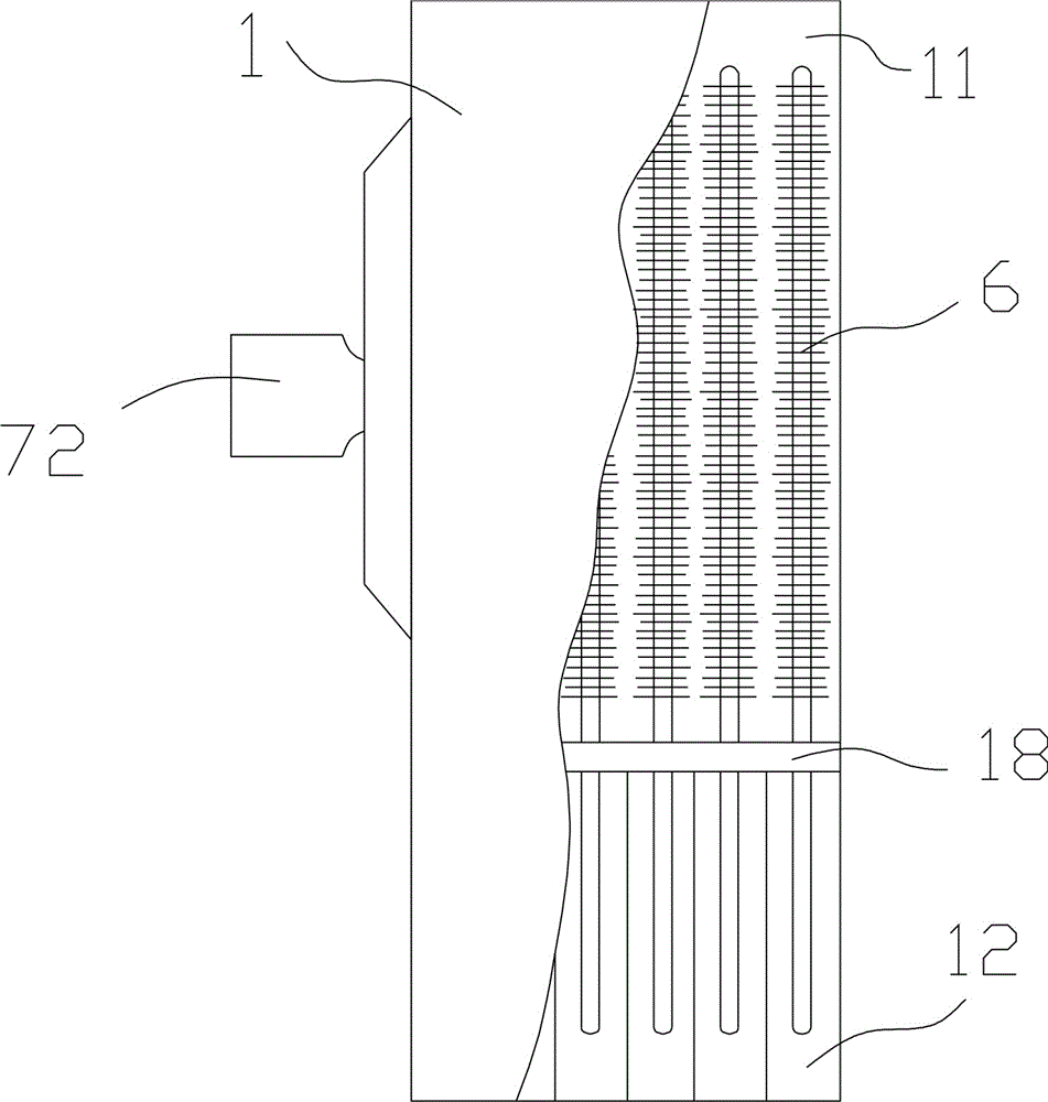
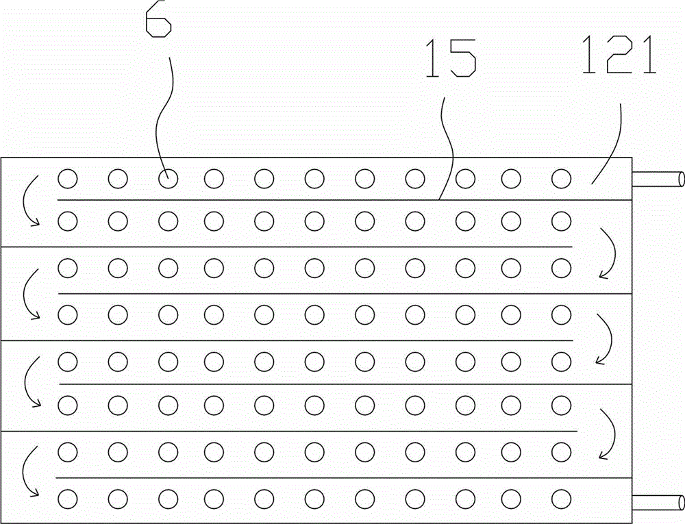
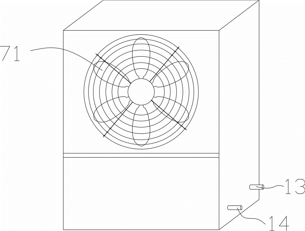
[0013] Such as Figure 1-4 As shown, a transformer superconducting heat pipe air-cooled heat exchanger includes a heat dissipation box 1 and a cold air device, and the heat dissipation box 1 is divided into an upper box 11 and a lower box 12 by a partition 18, and the lower box 12 is provided with There are oil inlets 13 and oil outlets 14; the lower box body 12 is provided with at least 8 guide plates 15 along the vertical direction, and the lower box body is divided into continuous bow-shaped flow guide grooves 121, which can To ensure that the space of the lower box is fully utilized, the longest flow time of the transformer oil is given to obtain the best heat dissipation...


PUM


Abstract

The invention discloses a cooling device for a transformer. The cooling device for the transformer comprises a cooling box body and a cold air device. The cooling box body is divided into an upper box body and a lower box body through a partition plate, and the lower box body is provided with an oil inlet and an oil outlet. At least eight flow guide plates are arranged in the lower box body in the vertical direction, and the lower box body is divided into continuous flow guide grooves arranged in the shape of a Chinese character 'gong'. Super-heat-conducting cooling tubes are evenly distributed in the flow guide grooves in the vertical direction and comprise tube bodies made of super-heat-conducting tubes, fixed parts fixed to the partition plate are arranged on the tube bodies and divide the tube bodies into cooling ends and heat absorbing ends from top to bottom, and cooling fins are arranged on the peripheries of the upper portions of the cooling ends. The heat absorbing ends are arranged in the flow guide grooves, and the cooling ends are placed in the upper box body after passing through the partition plate. The cold air device blowing air to the front side of the upper box body is arranged on the rear side of the upper box body, and an opening is formed in the front side of the upper box body. The cooling device for the transformer is good in cooling effect and convenient to maintain and avoids the accident of burning down of the transformer because mixing of oil and water is avoided.

Description

technical field [0001] The invention relates to the field of heat dissipation, in particular to a transformer superconducting heat pipe air-cooled heat exchanger. Background technique [0002] The heat dissipation of traditional transformers is mainly through the installation of water passages or oil passages in the body, and the heat is taken away by the circulating flow of cooling water or oil for heat dissipation. In addition, there are corresponding exhaust devices or hot oil and hot water circulation heat dissipation devices, which have a complex structure. , maintenance is difficult. The hot oil and hot water circulation heat dissipation device includes oil pipes and water pipes arranged adjacently. The water passing through the water pipes dissipates heat to the oil in the oil pipes. Mixed, thermally conductive transformer burnt. Contents of the invention [0003] In order to overcome the deficiencies of the prior art, the present invention provides a heat dissipa...

Claims


Application Information

Patent Timeline
Patent Type & Authority Patents(China)
IPC IPC(8): H01F27/08H01F27/12
Inventor 叶仁富
Owner ZHEJIANG BOTHWELL ELECTRIC
Why Eureka
Try Eureka