Pressure relief protected gear pump, manufacturing method and pressure relief protection method thereof

A gear pump and pressure relief technology, which is applied in pump control, pumps, rotary piston pumps, etc., can solve the problems of gear pumps that cannot be solved, complicated process, high cost, etc., and achieve the goal of avoiding motor burnout, high efficiency, and fast speed Effect

Active Publication Date: 2017-09-05
广东时光电子有限公司
View PDF6 Cites 0 Cited by
  • Summary
  • Abstract
  • Description
  • Claims
  • Application Information

AI Technical Summary

Problems solved by technology

Its shortcoming is: can't solve the problem that the pressure overload of the gear pump causes the pump to burst or the motor burns out
The traditional high-pressure gear pump design must process a metal cavity with a washing bed. In addition to the complicated process and high cost, based on the principle of the gear pump, the part that really has a vacuum effect is actually only half of the cavity
The gear cavity is mostly closed by fixed front and rear covers, so that when the vacuum pump body forms an overpressure, accidents such as pump burst or motor burnout are prone to occur

Method used


Image

  • Pressure relief protected gear pump, manufacturing method and pressure relief protection method thereof
  • Pressure relief protected gear pump, manufacturing method and pressure relief protection method thereof
  • Pressure relief protected gear pump, manufacturing method and pressure relief protection method thereof

Examples


Embodiment Construction

[0045] The present invention will be described in further detail below in conjunction with accompanying drawing:

[0046] Figure 1 to Figure 9 A first embodiment of the invention is shown.

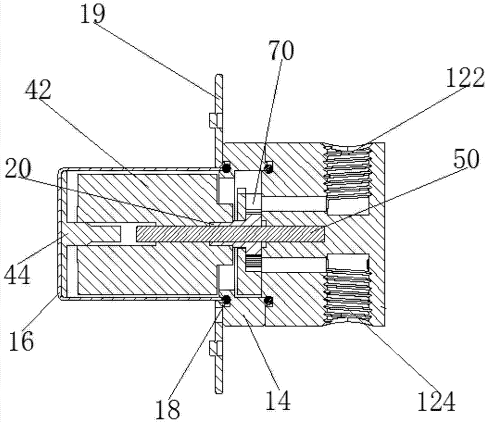
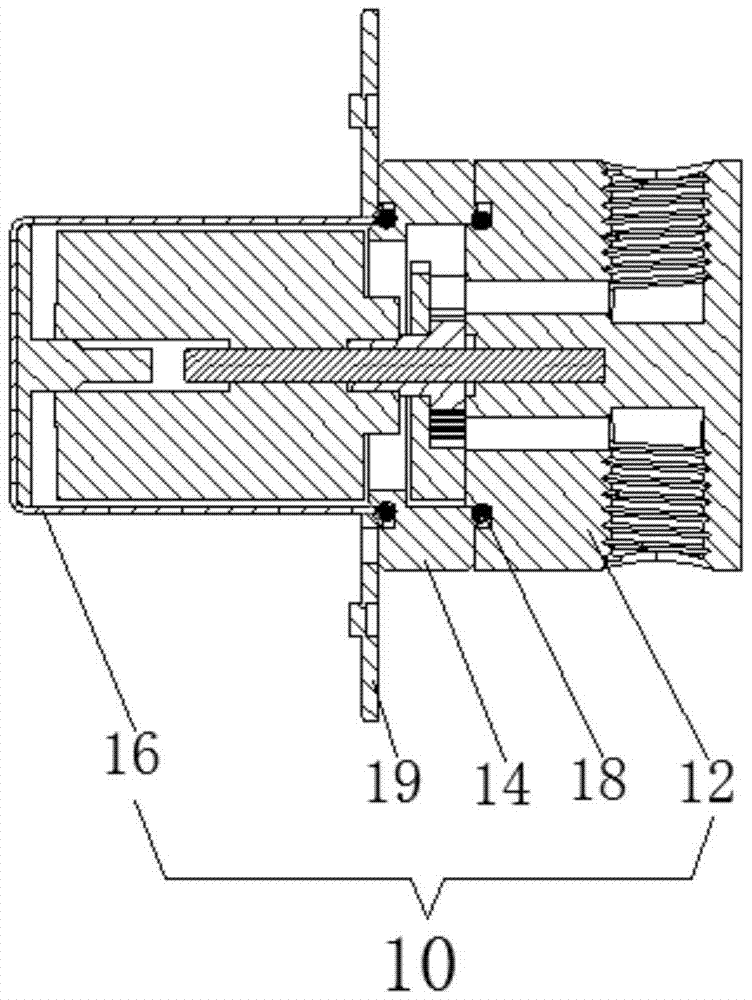
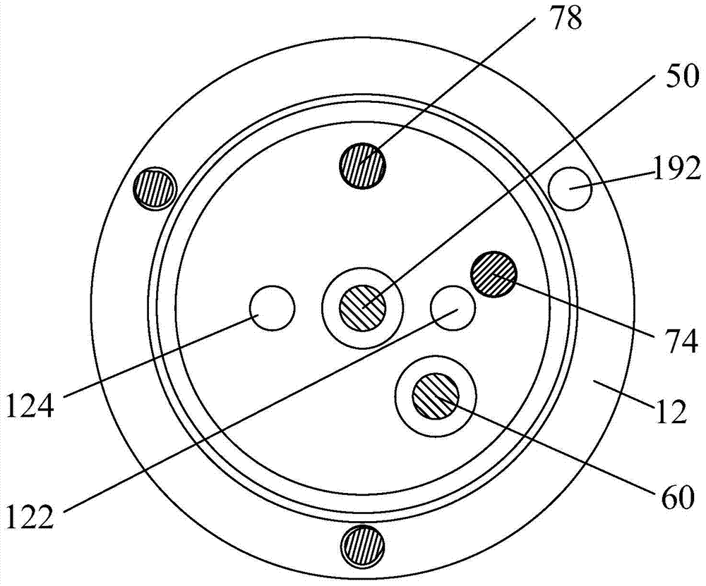
[0047] see Figure 1 to Figure 9 As shown, a pressure relief protection gear pump includes a pump body 10, a driving gear 20 and a driven gear 30 meshing with each other, and a power mechanism 40. The pump body 10 is provided with an inlet 122 and an outlet 124, and the driving gear 20 and the driven gear 30 are respectively positioned by the driving gear shaft 50 and the driven gear shaft 60, and the power mechanism 40 is connected to the driving gear shaft 50; the pump body 10 includes the pump head 12, the pump head ring 14 and the cover body 16 arranged in sequence, the driving gear 20 and the driven gear shaft. The gear 30 is set in the pump cavity formed inside the pump head ring 14, and the driving gear 20 and the driven gear 30 are respectively matched with the corresponding arc...


PUM


Abstract

The invention relates to a pressure relief protection gear pump, a manufacturing method and a pressure relief protection method thereof; the pressure relief protection gear pump includes a pump cavity, and a driving gear and a driven gear are arranged in the pump cavity to mesh with each other, and are located between the driving gear and the driven gear. The pump chamber at the top of the moving gear is provided with a floating valve that can be popped open for pressure relief when overloaded. The pressure relief protection method of the gear pump includes: (1) When the fluid entering the pump chamber causes the pressure in the pump chamber to exceed the elastic force of the floating valve, the valve is lifted to make the vacuum in the pump chamber disappear; (2) The fluid in the pump chamber moves along the pump chamber The inlet backflow, thereby releasing the pump chamber pressure, when the pump chamber pressure is less than the elastic force of the float valve, the valve will reset. The pump cavity of the present invention has a self-protection function. When the pressure in the pump cavity is overloaded, the floating valve plate can be popped open to release the pressure, so as to avoid accidents of pump burst or motor burnout caused by overpressure. This manufacturing method can reduce gear pump pressure. The technological process of production reduces the cost.

Description

technical field [0001] The invention relates to a fluid machine, in particular to a pressure relief protection gear pump, a manufacturing method and a pressure relief protection method thereof. Background technique [0002] The gear pump is a rotary pump that relies on the change and movement of the working volume formed between the pump cylinder and the meshing gear to deliver or pressurize the liquid. Existing gear pumps generally consist of two closed spaces, the pump body and the front and rear covers. When the gears rotate, the volume of the space on the side where the gears are disengaged increases from small to large, forming a vacuum, sucking the liquid, and the space on the side where the gears mesh The volume of the space changes from large to small, and the liquid is squeezed into the pipeline. Discharging the liquid is to release the pressure in the internal space. The pressure relief protection of the gear pump is particularly important because the overload of ...

Claims


Application Information

Patent Timeline
Patent Type & Authority Patents(China)
IPC IPC(8): F04C2/18F04C14/28
Inventor 刘平
Owner 广东时光电子有限公司
Why Eureka
Try Eureka