Voltage regulation method applicable to frequency conversion alternating-current generator

A technology of alternator and voltage regulation, which is applied to control the direction of the generator through the change of the magnetic field, and can solve the problems of small duty ratio of the excitation main power tube, instability, and poor system stability.

Active Publication Date: 2013-12-11
NANJING UNIV OF AERONAUTICS & ASTRONAUTICS
View PDF3 Cites 17 Cited by
  • Summary
  • Abstract
  • Description
  • Claims
  • Application Information

AI Technical Summary

Problems solved by technology

Therefore, there are two extreme situations in the case of frequency conversion: ①The open-loop gain of the forward channel of the system is very small at the lowest speed, and the stability of the system is very high at this time, but the dynamic performance of the voltage regulation system is particularly poor, and the steady-state error is relatively large; ② At the highest speed, the open-loop gain of the system's forward channel is very large. At this time, the stability of the system is particularly poor, and the voltage at the generator terminal will oscillate very violently, and even cannot be stabilized.
[0006] According to the two essential differences analyzed above, if it is applied in variable frequency alternator figure 1 The voltage regulator with the structure shown in will bring two problems: ① The duty ratio D of the excitation main power tube may not be enough at the lowest speed, and the duty cycle of the excitation main power tube is particularly small at the highest speed. Causes the output of the system to be particularly sensitive to interfering signals
②In the entire speed range, the voltage regulator can only have good control performance at certain speeds, and the control performance at other speeds will become worse, or even unstable

Method used


Image

  • Voltage regulation method applicable to frequency conversion alternating-current generator
  • Voltage regulation method applicable to frequency conversion alternating-current generator
  • Voltage regulation method applicable to frequency conversion alternating-current generator

Examples


Embodiment Construction

[0026] Below in conjunction with accompanying drawing, the technical scheme of invention is described in detail:

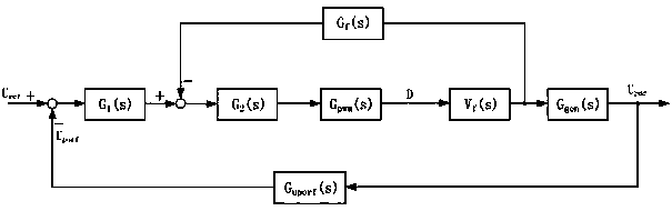
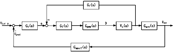
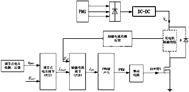
[0027] Based on the problems existing in the application of the constant frequency generator voltage regulation system in the variable frequency generator, the present invention adopts such as figure 2 shown in the control block diagram as well as image 3 The circuit block diagram shown realizes the voltage regulation of the variable frequency generator, which specifically includes the following steps:

[0028] Step 1, add a DC-DC converter between the permanent magnet auxiliary exciter and the AC exciter, and determine the input-output relationship of the DC-DC converter according to the no-load characteristic curve of the variable frequency generator:

[0029] where: V o is the DC-DC converter output voltage, V in Output excitation voltage for permanent magnet auxiliary exciter, U ref is the reference voltage of the variable frequency generator, n 额定 is...


PUM


Abstract

The invention discloses a voltage regulation method applicable to a frequency conversion alternating-current generator, and belongs to the technical field of three-level type frequency conversion alternating-current generators. According to the voltage regulation method, a one-level DC-DC converter is additionally arranged between a permanent magnet pilot exciter and an alternating-current exciter, the input-output characteristic curve of the DC-DC converter is designed, and when the voltage of the no-load end of the generator is a reference voltage at any rotating speed of the generator, the duty ratio of an excitation main power tube is constant. Meanwhile, open-loop gain of a forward path of a voltage regulation system can not be affected by the rotating speed of the generator.

Description

technical field [0001] The invention discloses a voltage regulation method suitable for a variable frequency alternator, and belongs to the technical field of a three-stage variable frequency alternator. Background technique [0002] The generator voltage regulator is a device that keeps the effective value of the generator output voltage constant. It is an important part of aircraft, ships and vehicles, and has always been valued by the production department. The control block diagram of most constant frequency generator voltage regulator systems is as follows: figure 1 . G 1 (s) is the voltage loop PID adjustment module, G 2 (s) is the PID adjustment module of the current loop, G PWM (s) is the generation module of PWM wave duty cycle D, V f (s) is the excitation voltage of the AC exciter, G gen (s) is the transfer function of the two-stage generator, G f (s) is the transfer function of the excitation winding, G uporf (s) is the transfer function of the voltage det...

Claims


Application Information

Patent Timeline
Patent Type & Authority Applications(China)
IPC IPC(8): H02P9/26
Inventor 杨善水彭方涛王莉付大丰张卓然
Owner NANJING UNIV OF AERONAUTICS & ASTRONAUTICS
Why Eureka
Try Eureka