
Constant-pressure drilling system of top drive drill winch and working method thereof

A drilling rig and top drive technology, which is applied in the field of geological drilling engineering, can solve problems such as low efficiency, slow feeding speed in drilling soft formations, and damage to drill bits

Inactive Publication Date: 2013-12-18
ANHUI LIANGHUAI KELI MACHINERY MFG
View PDF8 Cites 4 Cited by
  • Summary
  • Abstract
  • Description
  • Claims
  • Application Information

AI Technical Summary

Problems solved by technology

[0003] At present, the core drilling used in the field of geological drilling engineering is one of the main means of geological and mineral exploration. Due to the complex geological structure and many hard rock formations, the hardness of the drill bit is very high. Therefore, diamond drill bits are widely used in core drilling. The drill bit It has the advantages of high efficiency and long life. In actual operation, in order to make the diamond drill bit high in efficiency and long in life, it is necessary to control the pressure of the drill bit on the rock within a certain range. However, the feeding speed of the old model in the past depends on Guaranteed by the experience of the operator, it is very likely that the feed speed is too slow when drilling soft formations, and the efficiency is low; when drilling hard formations, the speed is too fast, and the pressure of the drill bit on the ground is too high, resulting in rapid damage to the drill bit

Method used


Image

  • Constant-pressure drilling system of top drive drill winch and working method thereof

Examples


Embodiment Construction

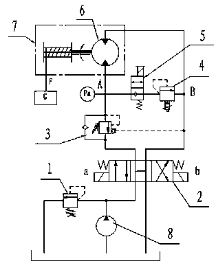
[0021] In order to facilitate the understanding of those skilled in the art, the present invention will be further described below in conjunction with the accompanying drawings. As a preferred embodiment of the present invention, please refer to figure 1 , a top drive drilling rig winch constant pressure drilling system has a hydraulic pump station, the hydraulic pump station includes a hydraulic pump 8, a manual reversing valve 2 and a drilling rig winch 7 driven by a winch motor 6. The hoist motor 6, the hydraulic pump 8, and the manual reversing valve 2 form a hydraulic oil circulation circuit through the hydraulic pipeline, and the manual reversing valve 2 is used to adjust the running direction of the hydraulic oil in the hoisting motor 6. A branch connected in parallel with the winch motor 6 is arranged on the hydraulic pipeline, and an electromagnetic cut-off valve 5 and a proportional overflow valve 4 are arranged in series on the branch. The input end of the winch mo...


PUM


Abstract

The invention relates to the technical field of geological drilling projects, in particular to a constant-pressure drilling system of a top drive drill winch and a working method thereof. The constant-pressure drilling system of the top drive drill winch comprises a hydraulic pump station, wherein the hydraulic pump station comprises a hydraulic pump, a manual reversing valve and a drill winch driven by a winch motor, a hydraulic oil circulating loop is formed by the winch motor, the hydraulic pump and the manual reversing valve through a hydraulic pipeline, and the manual reversing valve is used for adjusting an operating direction of hydraulic oil in the winch motor; a branch connected to the winch motor in parallel is arranged on the hydraulic pipeline, and an electromagnetic stop valve and a proportional overflow valve, which are connected in series, are arranged on the branch. According to the invention, through controlling drilling force during construction of a drill, the drill has constant feed force when the drill works, and the feed speed is automatically adjusted along with drilling complexity. When a soft stratum is drilled, quick drilling can be realized, and the drilling efficiency is not influenced; when a hard stratum is drilled, the speed is automatically reduced, so that the pressure of the drill on the stratum is not overlarge to destroy a drill bit quickly.

Description

[0001] technical field [0002] The invention relates to the technical field of geological drilling engineering, in particular to a hoisting constant pressure drilling system for a top drive drilling rig and a working method thereof. Background technique [0003] At present, the core drilling used in the field of geological drilling engineering is one of the main means of geological and mineral exploration. Due to the complex geological structure and many hard rock formations, the hardness of the drill bit is very high. Therefore, diamond drill bits are widely used in core drilling. The drill bit It has the advantages of high efficiency and long life. In actual operation, in order to make the diamond drill bit high in efficiency and long in life, it is necessary to control the pressure of the drill bit on the rock within a certain range. However, the feeding speed of the old model in the past depends on Guaranteed by the experience of the operator, it is very likely that the...

Claims


Application Information

Patent Timeline
IPC IPC(8): B66B1/08
Inventor 陆德义宋双进张随张明辉
Owner ANHUI LIANGHUAI KELI MACHINERY MFG
Learn More