
Humidifier

A humidifier and wet film technology, used in air humidification systems, heating methods, lighting and heating equipment, etc., can solve the problems of small humidifiers, large factory space, and inability to meet factories, and achieve good humidification effect and adsorption. Good effect, good water spray effect

Inactive Publication Date: 2013-12-18
SUZHOU KANGHUA PURIFYING SYST ENG
View PDF12 Cites 2 Cited by
  • Summary
  • Abstract
  • Description
  • Claims
  • Application Information

AI Technical Summary

Problems solved by technology

[0003] Faced with such extreme weather, many homes and factories have turned on air conditioners to lower the temperature, but the air conditioners only lower the temperature and cannot control the humidity in the air. Many people still feel uncomfortable
[0004] There are many humidifiers on the market, but these humidifiers are often relatively small in size and cannot meet the needs of the factory because the factory has a very large space
If there is a humidifier applicable to the environment of the factory, many problems can be solved, but there is no relevant description in the prior art

Method used


Image

  • Humidifier

Examples


Embodiment 1

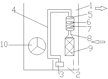
[0020] A humidifier, comprising a tank 1, a water tank 2, a water pump 3, a water pipe 4, a filter device 5, a shower 8, a wet film 9 and a fan 10, the water tank 2, the water pump 3, the water pipe 4, the filter device 5, The water shower 8, the wet film 9 and the fan 10 are all arranged in the box body 1, and the air inlet and the air outlet are arranged on the box body 1, wherein the water tank 2 is arranged at the bottom of the box body 1, and the water pipe 4 and the wet film 9 are fixedly connected to the On the side wall of the box body 1, one end of the water pipe is connected to the water pump 3 arranged in the water tank 2, the other end of the water pipe is connected to the filter device 5, and the other end of the filter device 5 is connected to the water shower 8, and the water shower 8 is located at Above the wet membrane 9, the water pumped out by the water pump 3 flows to the filter device 5 through the water pipe 4, and the filter device 5 filters the water, an...

Embodiment 2

[0023] A humidifier, comprising a tank 1, a water tank 2, a water pump 3, a water pipe 4, a filter device 5, a shower 8, a wet film 9 and a fan 10, the water tank 2, the water pump 3, the water pipe 4, the filter device 5, The water shower 8, the wet film 9 and the fan 10 are all arranged in the box body 1, and the air inlet and the air outlet are arranged on the box body 1, wherein the water tank 2 is arranged at the bottom of the box body 1, and the water pipe 4 and the wet film 9 are fixedly connected to the On the side wall of the box body 1, one end of the water pipe is connected to the water pump 3 arranged in the water tank 2, the other end of the water pipe is connected to the filter device 5, and the other end of the filter device 5 is connected to the water shower 8, and the water shower 8 is located at Above the wet membrane 9, the water pumped out by the water pump 3 flows to the filter device 5 through the water pipe 4, and the filter device 5 filters the water, an...


PUM


Abstract

The invention discloses a humidifier, which comprises a cabinet, a water tank, a water pump, a water pipe, a filter unit, a water sprinkler, a wet film and a fan, wherein the water tank is arranged at the bottom part of the cabinet; the water pipe and the wet film are fixedly connected onto the side wall of the cabinet; one end of the water pipe is connected with the water pump arranged in the water tank; the other end of the water pipe is connected with the filter unit; the other end of the filter unit is connected with the water sprinkler; the water sprinkler is located above the wet film; water pumped out by the water pump flows to the filter unit by the water pipe; the water is filtered by the filter unit; the filtered water is sprinkled into the wet film by the water sprinkler; the fan is located at the rear of the wet film; air in front of the wet film is blown out from an air outlet after being sucked into the cabinet from an air inlet. According to the humidifier disclosed by the invention, the air is humidified by the wet film, and after the air passes through the wet film, the humidity can be greatly increased, and a humidifying effect is good.

Description

technical field [0001] The invention belongs to humidification equipment, in particular to a humidifier. Background technique [0002] With the intensification of global warming, more and more places fall into hot weather in summer, with an average temperature of around 40 degrees and a ground temperature of around 65 degrees. Such weather will cause great damage to people's bodies. Many people suffer from heat stroke, and their body temperature exceeds the maximum value of the thermometer. Many people die of heatstroke. [0003] Faced with such extreme weather, many homes and factories have turned on air conditioners to lower the temperature. However, air conditioners only lower the temperature and cannot control the humidity in the air. Many people still feel uncomfortable. [0004] There are many humidifiers on the market, but these humidifiers are often relatively small in size and cannot meet the needs of the factory because the factory has a very large space. If ther...

Claims


Application Information

Patent Timeline
IPC IPC(8): F24F6/04F24F13/28
Inventor 葛卫平陈宗美
Owner SUZHOU KANGHUA PURIFYING SYST ENG
Learn More