crimp terminal

A technology of crimping terminals and slits, applied in the direction of connection, contact parts, conductive connection, etc., can solve the problem of inapplicable crimping terminals, etc., and achieve the effect of ensuring contact reliability and easy inventory management

Active Publication Date: 2016-12-28
ORMON CORP
View PDF7 Cites 0 Cited by
  • Summary
  • Abstract
  • Description
  • Claims
  • Application Information

AI Technical Summary

Problems solved by technology

Therefore, there is a problem that the crimp terminal cannot be applied to a crimp terminal used on a connector whose pushing amount is fixed

Method used


Image

  • crimp terminal
  • crimp terminal
  • crimp terminal

Examples


Embodiment Construction

[0038] The following will be based on the attached Figure 1A to Figure 13B Embodiments of the crimp terminal according to the present invention will be described.

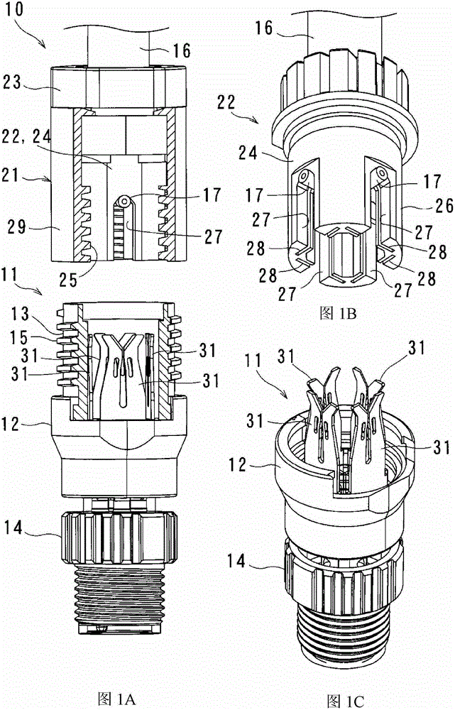
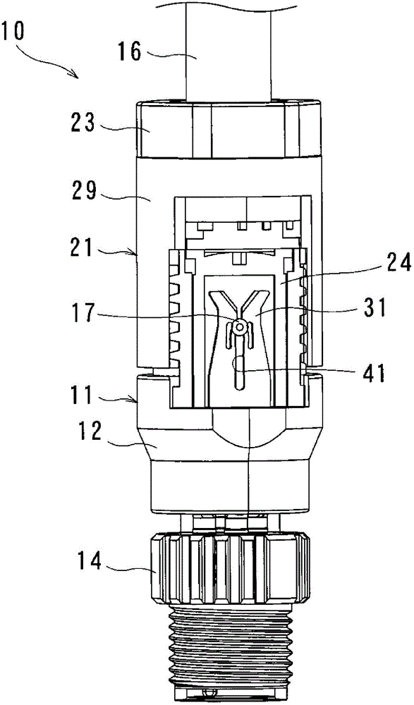
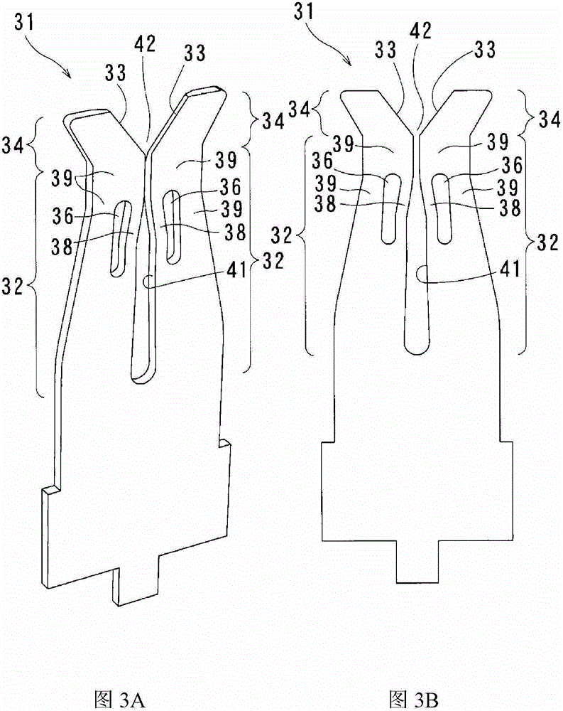
[0039] The first embodiment is a case where the crimp terminal 31 of the present invention is applied to a connector 10 formed by connecting a plug 11 and a receptacle 21, as Figure 1A to Figure 1C as well as figure 2 shown.

[0040] The plug 11 includes a cylindrical plug body 12, a cylindrical plug housing 13 engaged with the plug body 12 to extend upward, and a fastening portion 14 for fastening a cable (not shown) on the lower end side of the plug body 12. . In the plug main body 12, four crimping terminals 31 according to the present invention are arranged and fixed so as to form one side of a regular square respectively (refer to Figure 1C ), and is electrically connected to the cable. Such as Figure 1A As shown, male threads 15 are formed on the outer circumference of the plug housing 13 . It shou...


PUM


Abstract

The present invention provides a crimping terminal capable of crimping and holding multiple types of electric wires having different diameters by a fixed pushing amount. Therefore, a slit for pressing and holding the conductor is provided between the pair of spring portions in the crimp terminal and the upper edge of the conductor, and the conductor held by the slit is placed in contact with the conductor. At fixed positions where the openings of the slits are separated by a distance, there is provided a region in which at least one of the pair of spring parts arranged on the underside of the upper edge of the conductor The cross-sectional area is smaller than that of the spring portion at the position of the upper edge of the electrical conductor.

Description

[0001] Cross References to Related Applications [0002] This application claims the benefit of priority from Japanese Patent Application No. 2012-124639 filed on May 31, 2012, the entire contents of which are incorporated herein by reference. technical field [0003] The present invention relates to a crimping terminal for crimping and connecting electric wires or the like into, for example, U-shaped crimping seams for trunk connection with sensors and the like. Background technique [0004] Conventionally, in order to use a connector for connecting electric wires, it is recommended to use a variety of terminals to crimp a plurality of electric wires having different diameters. For example, Japanese Unexamined Patent Publication No. 2005-166653 describes a connector using, as such a terminal, a crimp terminal in which a slit of a fixed width is formed. However, in the case of crimping an electric wire having a small diameter, this crimping terminal has problems of insuffic...

Claims


Application Information

Patent Timeline
Patent Type & Authority Patents(China)
IPC IPC(8): H01R13/02H01R13/193H01R4/18
CPCH01R4/2433H01R4/2466H01R4/48
Inventor 的场正人赤堀隼祐
Owner ORMON CORP
Why Eureka
Try Eureka