Lockable ejection device with overload mechanism

A technology that pushes out the device and closes the position. It is applied in the direction of household appliances, furniture parts, drawers, etc., and can solve problems such as undesired unlocking and channel widening.

Active Publication Date: 2013-12-18
JULIUS BLUM GMBH
View PDF6 Cites 0 Cited by
  • Summary
  • Abstract
  • Description
  • Claims
  • Application Information

AI Technical Summary

Problems solved by technology

The disadvantage here is that the flexible material can wear out during multiple overload movements by the control pin being squeezed through, whereby an undesired widening of the channel can occur
Undesired unlocking can thus already take place even with normal load or a small overload

Method used


Image

  • Lockable ejection device with overload mechanism
  • Lockable ejection device with overload mechanism
  • Lockable ejection device with overload mechanism

Examples


Embodiment Construction

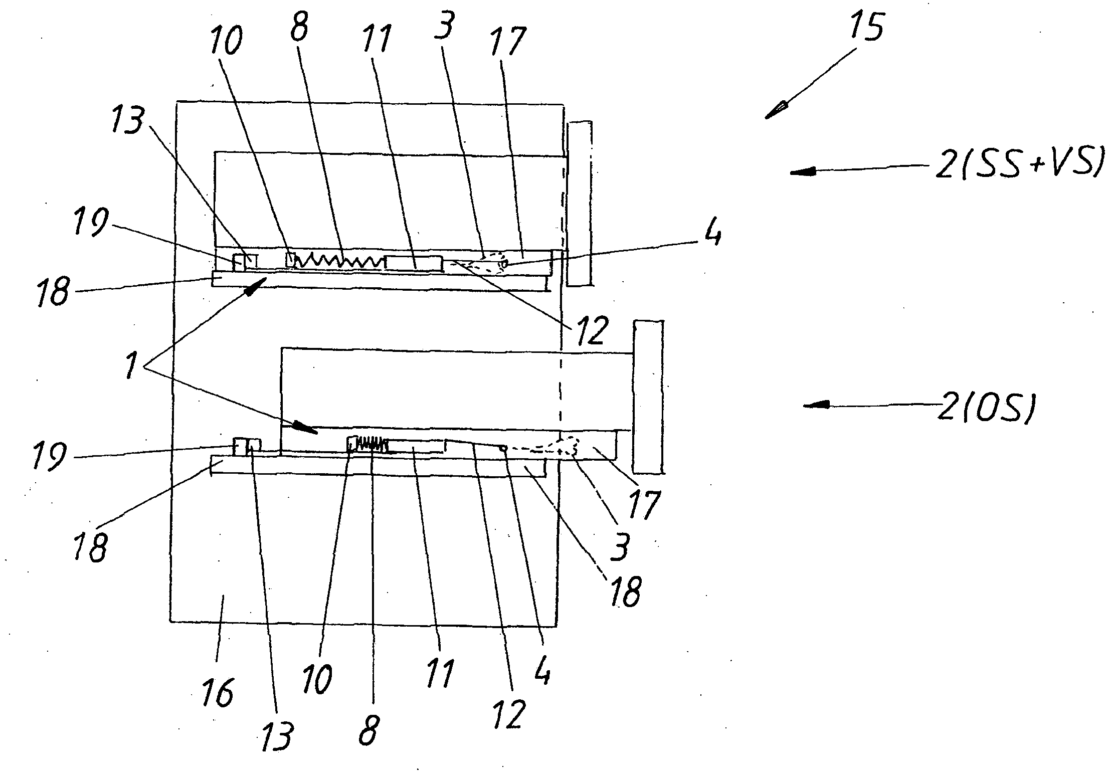
[0032] figure 1 A piece of furniture 15 is shown, which comprises a furniture body 16 and two movable furniture parts 2 . In this case, the upper movable furniture part 2 is in the closed position SS, wherein the control bolt 4 is held in the locked position VS in the slideway 3 . The control pin 4 is connected via a control rod 12 to a slide 11 which is displaceable in a housing 10 (shown only schematically here). The carriage 11 is connected to the housing 10 via an ejection spring 8 , wherein the ejection spring 8 (tension spring) is tensioned in the locked position VS. The ejection device 1 is mounted on the drawer rail 17, wherein the drawer rail 17 is locked relative to the main body rail 18, i.e. cannot be moved, since the drawer rail 17 is held on the main body by the ejection device 1 and its ejection element 13 (with locking hooks) On the driving part 19 of the guide rail 18.

[0033] If now (as in figure 1 (shown in the lower movable furniture part 2 ) (possible...


PUM


Abstract

The invention relates to a lockable ejection device (1) for a movable furniture part (2), having a control pin (4) movable in a cardioid-shaped slotted guide track (3). The slotted guide track (3) comprises a closing section (3a), in which the control pin (4) moves as the movable furniture part (2) is closed, a locking section (3b) having a latching depression (5) in which the control pin (4) is held in the locked position (VS), and an opening section (3c) in which the control pin (4) is movable as the mobile furniture part is opened. An overload mechanism (6), by means of which the locked position (VS) can be released even upon movement of the movable furniture part (2) in the opening direction (OR), is arranged in the locking section (3b), wherein the overload mechanism (6) comprises a blocking element (7), to which force is applied and which temporarily blocks an overload path (W) for the control pin (4), wherein the blocking element (7) at least partially forms the latching depression (5) of the locking section (3b) and the overload path (W) that can be blocked by the blocking element (7) leads through a channel defined by a channel wall, through which channel the control pin (4) is able to travel in the event of overload. The spatial relation of the channel to the closing section (3a) and the opening section (3c) is fixed and the channel opens into the opening section (3a), wherein the blocking element (7) is formed separately from the channel wall and is movable in the channel.

Description

technical field [0001] The invention relates to a lockable ejection device for movable furniture parts, the ejection device comprising a control pin displaceable in a heart-shaped slideway, wherein the slideway has a closing section, When moving furniture parts, the control bolt moves in the closing section; the locking section with the locking groove, in the closed position, the control bolt is held in the blocking section; and the opening section, when opening the movable In the case of a piece of furniture, the control bolt can be moved in this opening section; wherein an overload mechanism is arranged in the locking section, by means of which the locked position can be released even when the movable furniture part moves in the opening direction, wherein , the overload mechanism has a force-loaded locking element for temporarily locking the overload path of the control pin. Background technique [0002] Lockable ejection devices (also referred to as touch latches) are us...

Claims


Application Information

Patent Timeline
Patent Type & Authority Applications(China)
IPC IPC(8): A47B88/04
CPCA47B88/463A47B88/57
Inventor H·布伦迈尔
Owner JULIUS BLUM GMBH
Why Eureka
Try Eureka