
Belt conveyor centralized control method and system

A centralized control system and belt conveyor technology, applied in the centralized control method and system field of belt conveyors, can solve problems such as buried pressure, failure to realize frequency conversion operation of belt conveyors, and inability to truly reflect the coal flow rate of belt conveyors, etc.

Active Publication Date: 2013-12-25
CHINA SHENHUA ENERGY CO LTD +1
View PDF11 Cites 7 Cited by
  • Summary
  • Abstract
  • Description
  • Claims
  • Application Information

AI Technical Summary

Problems solved by technology

In this way, the tape machine is still in a light-load state most of the time, and the power saved is only to solve the problem of unreasonable matching between production capacity and transport capacity.
Therefore, in actual work, manual intervention in the frequency conversion mode is rarely used, and the tape machine is always in the power frequency working mode. The frequency converter only plays the role of soft start, and cannot realize the frequency conversion operation of the tape machine.
[0010] If the automatic frequency conversion method of the existing technology is adopted, because the coal flow of each working face in the mine is in production, the coal flow of each working face is unstable, and the load of the belt conveyor cannot truly reflect the coal flow on the belt conveyor, and coal flow often occurs. Phenomenon
For example, if the fully mechanized mining face suddenly changes from knife feed to normal coal mining, due to the sudden and large increase in coal flow, when the greatly increased coal flow reaches the tail of the belt conveyor, since the total amount of coal on the belt conveyor is still small at this time, the load monitoring of the belt conveyor It shows that the load is still light, and the tape machine is still running at a low speed, and the instantaneous coal flow may cause the tail accident of the buried tape machine
Therefore, the function of automatic frequency conversion with the load of the tape machine has not been realized in actual production.

Method used


Image

  • Belt conveyor centralized control method and system
  • Belt conveyor centralized control method and system
  • Belt conveyor centralized control method and system

Examples


Embodiment Construction

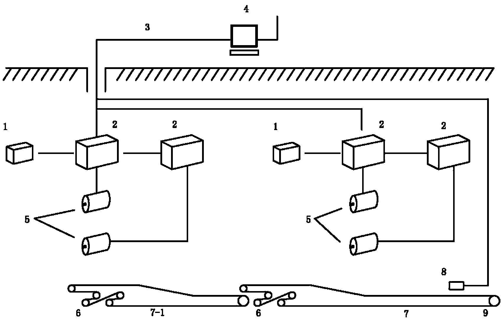
[0020] As shown in 1, the tape machine is driven by the traction motor 5, and the power of the traction motor 5 determines the running speed of the tape machine. The traction motor 5 is electrically connected to the frequency converter 2 , and the frequency converter 2 controls the working frequency of the traction motor 5 . The frequency converter 2 can be controlled by the technician at the console 1 locally, more advantageously, controlled by the ground control device 4 . The frequency converter 2 communicates with the ground control device 4 through an optical cable 3 .

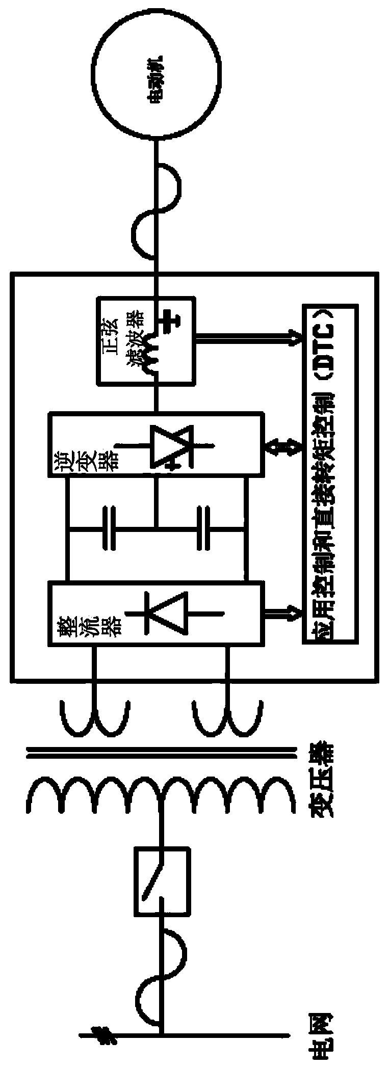
[0021] figure 2 shown figure 1 Inverter 2 structure and principle of frequency conversion. The frequency converter 2 is a power control device that converts the commercial frequency power supply to another frequency by using the on-off function of the power semiconductor device. A device that transforms the power frequency power supply (50Hz or 60Hz) into AC power supplies of various frequencies thro...


PUM


Abstract

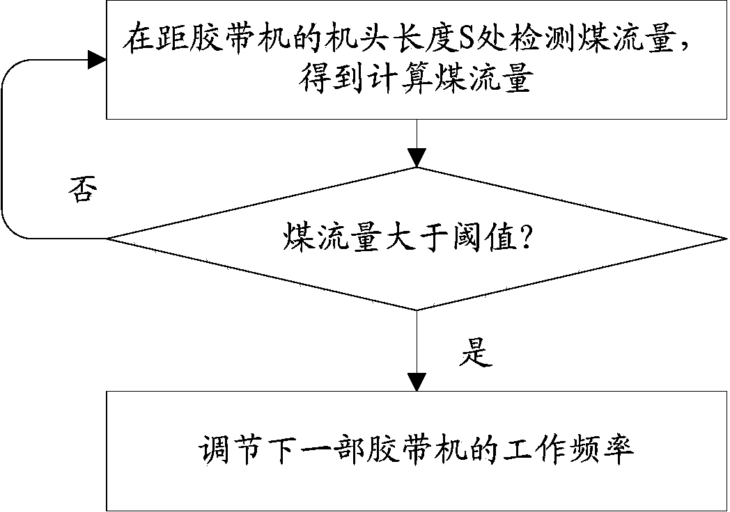
A belt conveyor centralized control method comprises 1) measuring coal flow at a position S away from the machine head of a belt convey to obtained calculated coal flow amount; 2) according to the comparison result of the calculated coal flow amount and a threshold value to adjust the working frequency of a next belt conveyor. The invention also provides a belt conveyor centralized control system. The belt conveyor centralized control method and system enables every belt conveyor to perform automatic frequency variation reaction to coal flow to be increased or reduced in advance, avoids machine tail burying accidents caused by abrupt coal flow increase due to production imbalance, achieves real-time matching of the belt conveyors and the actual output of a mine and further achieves frequency variation in the true sense.

Description

technical field [0001] The present invention relates to the operation technology of the tape machine, more specifically, to the centralized control method and system of the tape machine. Background technique [0002] In the transportation work of coal mining area, conveyors are widely used, including belt conveyors (belt conveyors) and chain conveyors. Due to the long distance from the working face to the coal bunker in the mining area, sometimes there are as many as 10 conveyors, which are called the mining area transportation system. Each conveyor in the entire transportation system can be controlled individually (that is, manual local control), or centralized control (that is, one driver controls the entire transportation system). [0003] Manual local control means that the control of each conveyor is operated by a driver on the spot, which is the most primitive control method. This control method is to directly operate the control switch of the conveyor. The operation...

Claims


Application Information

Patent Timeline
Patent Type & Authority Applications(China)
IPC IPC(8): B65G43/00
Inventor 周成军
Owner CHINA SHENHUA ENERGY CO LTD
Learn More