
A top entry ball valve with adjustable seat

A top-loading and adjustable technology, applied in valve devices, cocks including cut-off devices, engine components, etc., can solve problems such as easy leakage points, unreasonable structure, etc., and achieve the effect of optimal sealing effect.

Active Publication Date: 2016-06-29
XUANDA IND GRP
View PDF6 Cites 0 Cited by
  • Summary
  • Abstract
  • Description
  • Claims
  • Application Information

AI Technical Summary

Problems solved by technology

[0004] In order to solve the problem that the existing top-entry ball valve has easy leakage points due to unreasonable structure, the present invention provides a top-entry ball valve with an adjustable valve seat. The adjustable valve seat changes the seat structure and adopts a built-in type with The advantages of easy operation and no leak point

Method used


Image

  • A top entry ball valve with adjustable seat
  • A top entry ball valve with adjustable seat

Examples


Embodiment Construction

[0013] Embodiments of the present invention will be further described below in conjunction with accompanying drawings:

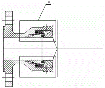
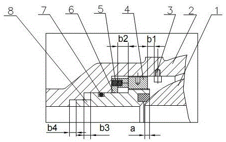
[0014] Such as figure 1 or figure 2 As shown, a top-entry ball valve with an adjustable valve seat includes a valve seat 8 that can move left and right, a valve body 2, a ball 1 and an adjusting nut 4. The valve seat 8 is installed inside the valve body 2, and the adjusting nut A limiting block 3 is provided between 4 and the ball 1, a limiting device is provided between the adjusting nut 4 and the valve body 2, and the valve seat 8 and the adjusting nut 4 form a screw fit.

[0015] The limiting device includes a spring seat 5 and a spring 6. One end of the spring 6 is connected to the spring seat 5, and the other end is connected to the valve body 2. The left side of the spring seat 5 is in contact with the valve body 2, and the right side is in contact with the adjusting nut 4. The bottom surface is in contact with the valve seat 8.

[0016] The adjust...


PUM


Abstract

The invention relates to a top-loading ball valve with an adjustable valve seat, which comprises a valve seat that can move left and right, a valve body, a ball and an adjusting nut. There is a limit device between the adjusting nut and the valve body. The valve seat and the adjusting nut form a spiral fit. The adjustable valve seat uses a built-in adjusting nut to control the left and right movement of the valve seat, so that the ball valve No leakage point, safer and more reliable. For occasions with low pressure difference or high sealing requirements, the forced sealing force can be provided through the adjusting nut to achieve a better sealing effect, and the self-relieving function of the valve cavity can also be provided.

Description

technical field [0001] The invention relates to a valve, in particular to a top entry ball valve with an adjustable valve seat. Background technique [0002] The ball adopts the top entry ball valve loaded from the middle cavity, which has the advantages of two-way sealing, online maintenance, less external leakage points and long service life of the valve, so it is widely used in many important working conditions. The key point of this valve structure is: the valve adopts a split structure in which the sealing ring is embedded on the metal valve seat. In order to ensure that the ball can be smoothly inserted from the middle cavity, when the ball is installed, the valve seats on both sides are first moved outward. After a certain distance, after the ball is installed in place, the valve seats on both sides will reset and be in close contact with the ball, creating a sealing effect between the ball and the valve seat. [0003] At present, most of the traditional implementati...

Claims


Application Information

Patent Timeline
Patent Type & Authority Patents(China)
IPC IPC(8): F16K5/06F16K5/20
Inventor 史庆泰胡建龙魏明珍
Owner XUANDA IND GRP
Learn More