
Backlight drive circuit and television

A driving circuit and backlight technology, which is applied in the direction of light source, electric light source, electric lamp circuit arrangement, etc., can solve the problems of inability to guarantee the constant current driving of the backlight source load, unfavorable industrial production, and high manufacturing cost, so as to improve reliability and reduce production. cost, the effect of realizing constant current control

Active Publication Date: 2013-12-25
GUANGDONG HISENSE ELECTRONICS CO LTD
View PDF5 Cites 12 Cited by
  • Summary
  • Abstract
  • Description
  • Claims
  • Application Information

AI Technical Summary

Problems solved by technology

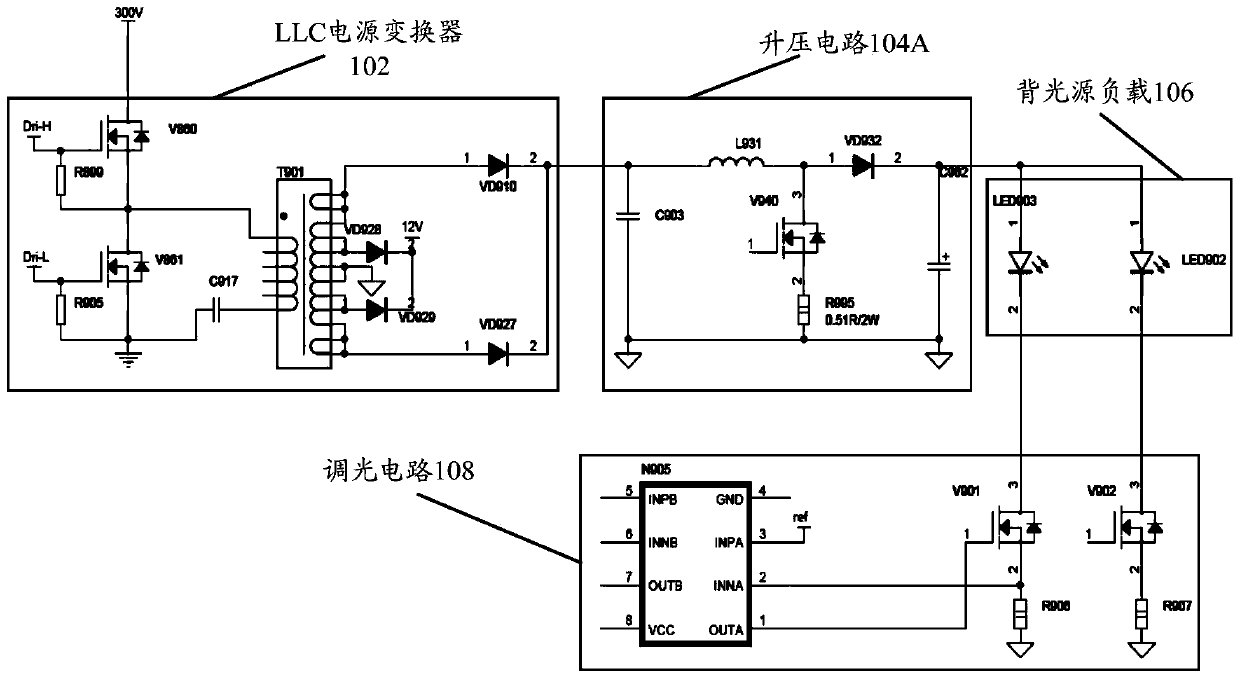
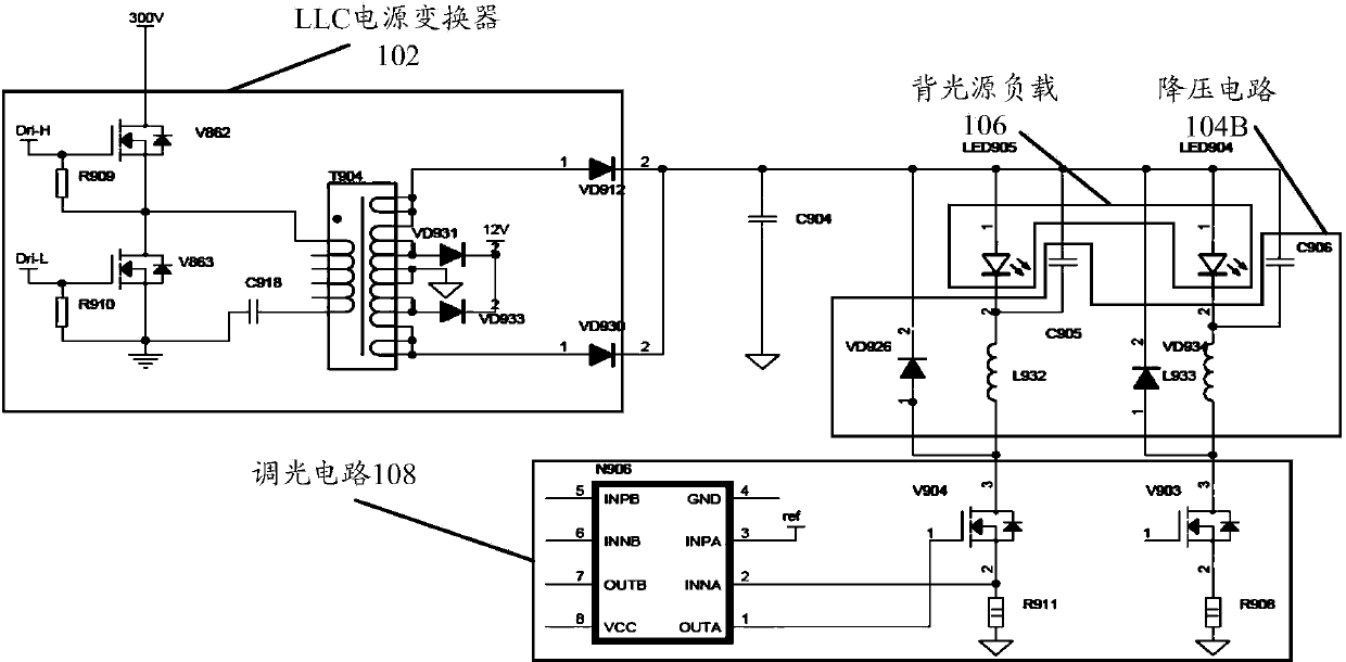
[0004] Because the LLC power converter 102 needs to provide stable voltages such as 12V and 18V for the main board and audio, so that when it outputs voltage to the backlight load at the same time, the voltage is very unstable and cannot guarantee the constant current drive of the backlight load. After the DC-DC conversion such as the BOOST step-up circuit 104A or the BUCK step-down circuit 104B, it can be used for constant current driving of the backlight load, making the whole circuit more loaded, and the manufacturing cost is high, which is not conducive to actual industrial production.

Method used


Image

  • Backlight drive circuit and television
  • Backlight drive circuit and television
  • Backlight drive circuit and television

Examples


Embodiment Construction

[0023] In order to understand the above-mentioned purpose, features and advantages of the present invention more clearly, the present invention will be further described in detail below in conjunction with the accompanying drawings and specific embodiments. It should be noted that, in the case of no conflict, the embodiments of the present application and the features in the embodiments can be combined with each other.

[0024] In the following description, many specific details are set forth in order to fully understand the present invention, but the present invention can also be implemented in other ways different from those described here, therefore, the present invention is not limited to the specific embodiments disclosed below limit.

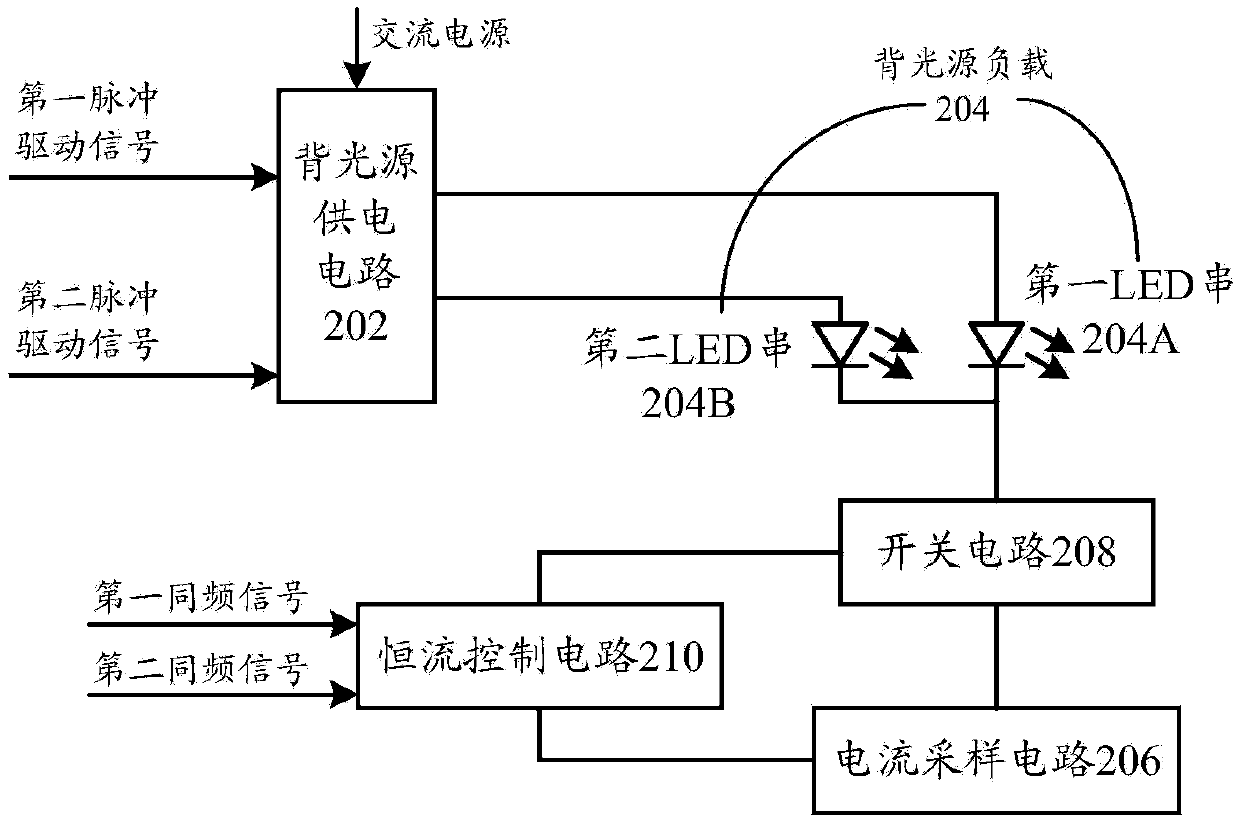
[0025] Figure 2A A schematic structural diagram of a backlight driving circuit according to an embodiment of the present invention is shown.

[0026] Such as Figure 2A As shown, the backlight driving circuit according to an embodiment...


PUM


Abstract

The invention provides a backlight drive circuit which comprises a backlight power supply circuit, a current sampling circuit, a switching circuit and a constant-current control circuit. The backlight power supply circuit provides voltages needed in working to backlight loads according to received pulse drive signals. The current sampling circuit is used for carrying out sampling on the working currents of the backlight loads. The switching circuit is arranged on negative side lines of the backlight loads, and is used for controlling the switching on or off of the negative side lines of the backlight loads. The constant-current control circuit is connected to the current sampling circuit and the switching circuit, and is used for controlling the duty ratio of the switching circuit in a conducting state according to the intensity of the working currents of the backlight loads collected by the current sampling circuit, so that the numerical value of the average working current of the backlight loads is made to be equal to a preset current threshold. The invention further provides a television. Through the technical scheme, the constant-current control over the backlight loads can be achieved.

Description

technical field [0001] The present invention relates to the technical field of backlight driving, in particular to a backlight driving circuit and a television. Background technique [0002] In order to simplify the circuit structure and make full use of the existing circuits, it is proposed in the related art that the LLC circuit is used to drive the backlight load and at the same time to drive the motherboard, audio and other peripherals. [0003] Such as Figure 1A As shown, it is a circuit structure used to achieve the above purpose in the related art, the circuit includes: LLC power converter 102, (BOOST) step-up circuit 104A, backlight load 106, dimming circuit 108, etc.; Figure 1B Shown is another circuit structure used to achieve the above purpose in the related art, the circuit includes: LLC power converter 102, (BUCK) step-down circuit 104B, backlight load 106, dimming circuit 108 and so on. [0004] Because the LLC power converter 102 needs to provide stable vol...

Claims


Application Information

Patent Timeline
Patent Type & Authority Applications(China)
IPC IPC(8): H05B37/02
Inventor 高宽志王清金
Owner GUANGDONG HISENSE ELECTRONICS CO LTD
Learn More