
Driving circuit based on flyback conversion power supply

A technology of drive circuit and power supply voltage, applied in the direction of adjusting electrical variables, control/regulation systems, instruments, etc., can solve problems such as increasing process complexity, achieve low surface temperature, ensure stability, and be easy to transplant

Inactive Publication Date: 2016-11-23
成都元始信息科技有限公司
View PDF1 Cites 0 Cited by
  • Summary
  • Abstract
  • Description
  • Claims
  • Application Information

AI Technical Summary

Problems solved by technology

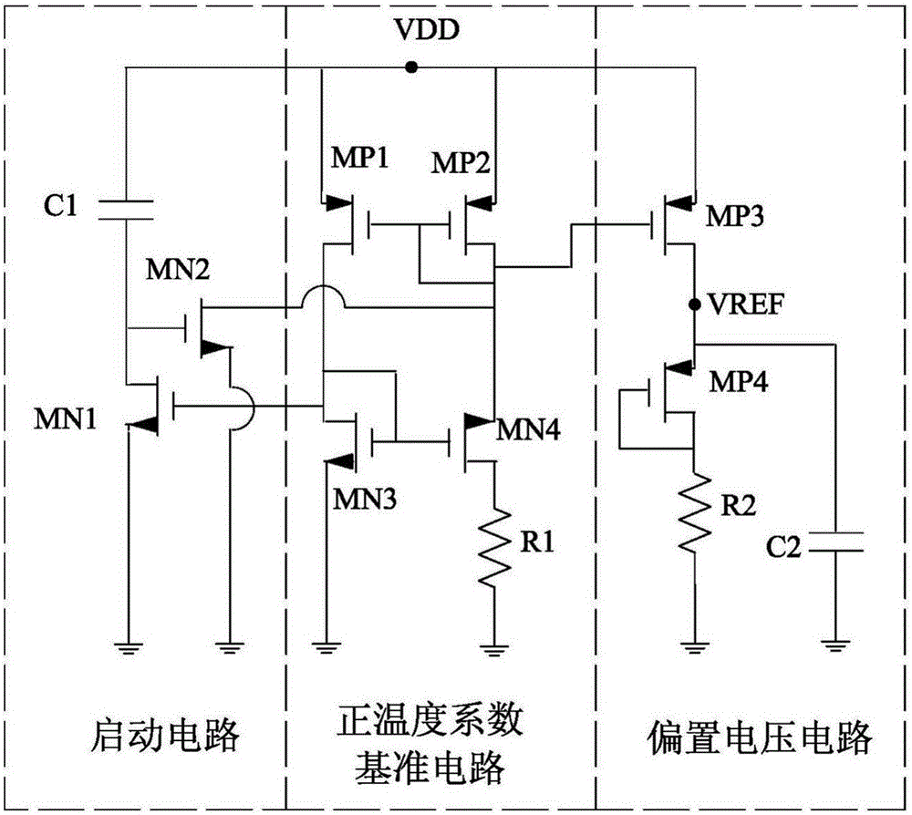
In this patent, the depletion MOS tube and the enhancement MOS tube are used at the same time, which will increase the complexity of the process, and most processes do not provide these two MOS tubes at the same time.

Method used


Image

  • Driving circuit based on flyback conversion power supply
  • Driving circuit based on flyback conversion power supply
  • Driving circuit based on flyback conversion power supply

Examples


Embodiment 1

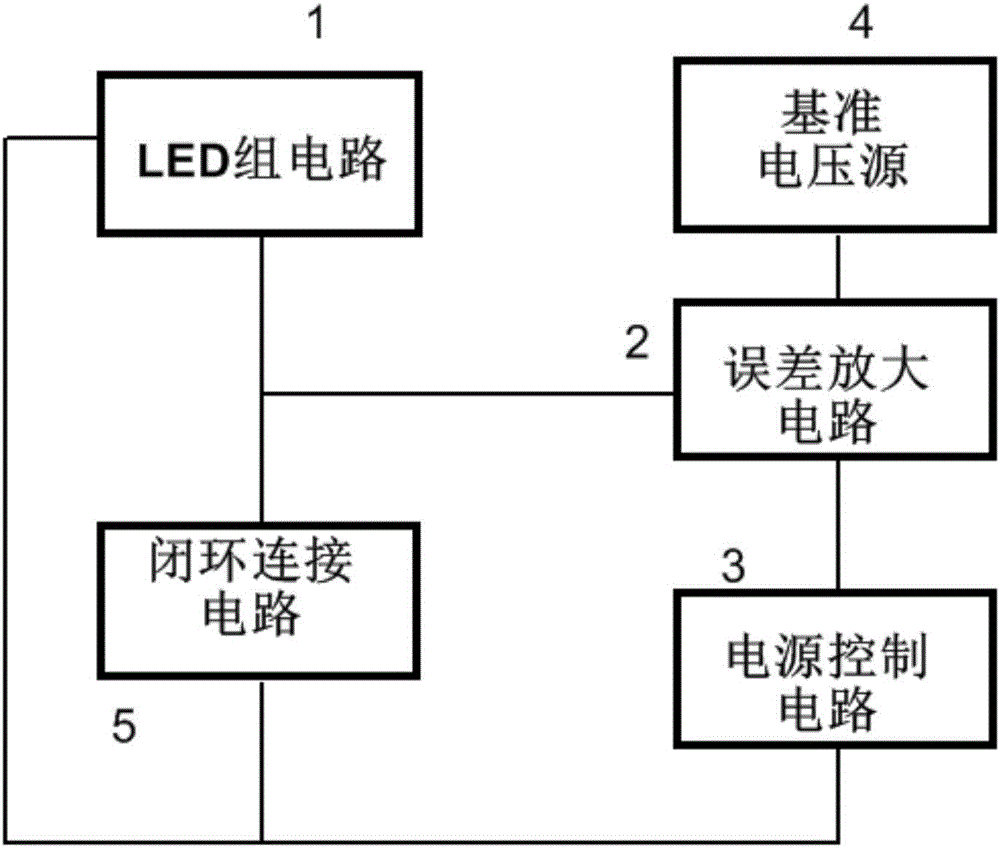
[0038] The voltage divider circuit includes a fourth resistor, a fifth resistor, and a fourth capacitor; the first end of the fourth resistor is connected to the reference voltage source, and the second end of the fourth resistor is connected to the fifth resistor. The first end; the first end of the fifth resistor is connected to the second voltage signal input end of the error amplifier circuit, and the second end of the fifth resistor is grounded; the fourth capacitor is connected in parallel with the fifth resistor .

[0039] The LED drive circuit further includes an RC filter circuit; the signal acquisition end of the LED group circuit is connected to the first voltage signal input end of the error amplifier circuit through the RC filter circuit.

[0040] The RC filter circuit includes a sixth resistor and a fifth capacitor; the first end of the sixth resistor is connected to the signal collection end of the LED group circuit, and the second end of the sixth resistor is con...


PUM


Abstract

The invention relates to the technical field of LED drivers, in particular to a driving circuit based on a flyback conversion power supply. The technical problem that a driving circuit in the prior art is greatly influenced by temperature variation is solved. The driving circuit mainly comprises an LED set circuit, an error amplifying circuit, a supply voltage control circuit, a reference voltage source and a closed loop connection circuit. The LED set circuit comprises an LED lamp bead assembly and a heat conducting rod, the LED lamp bead assembly is installed on the outer wall of the heat conducting rod, and heat conductors are installed at one or two ends of the heat conducting rod.

Description

technical field [0001] The invention relates to the technical field of LED driving, in particular to a driving circuit based on a flyback conversion power supply. Background technique [0002] The constant current drive is to adjust the size of the power supply voltage by collecting the sampling voltage of the LED to form a closed loop, so that the current passing through the LED is stable. However, since the LED itself has a turn-on voltage, when the power supply voltage is just started, it is not enough to make the LED turn on, so the sampling voltage output of the LED is zero, causing the LED drive circuit to open the loop. Therefore, the rapid rise of the power supply voltage is not controlled, and the phenomenon of output overshoot occurs, which may cause the LED to burn out in severe cases. [0003] In order to obtain a stable power supply voltage, it is necessary to provide a stable reference voltage. From the above introduction, the reference voltage value obtained ...

Claims


Application Information

Patent Timeline
Patent Type & Authority Applications(China)
IPC IPC(8): G05F1/575
CPCG05F1/575
Inventor 姚海林范娟秀任无
Owner 成都元始信息科技有限公司
Learn More