Airborne scanning radar imaging method in iteration compression mode

A scanning radar, compressed mode technology, applied in the field of radar, can solve the problems of target amplitude distortion, affecting target, position offset and so on

Active Publication Date: 2014-01-01
UNIV OF ELECTRONICS SCI & TECH OF CHINA
View PDF1 Cites 24 Cited by
  • Summary
  • Abstract
  • Description
  • Claims
  • Application Information

AI Technical Summary

Problems solved by technology

When there are multiple targets in the scene, this method will cause target amplitude distortion, position offset, and false targets due to noise amplification. These phenomena will affect the performance of target detection, positioning and recognition, and bring serious consequences to practical applications.

Method used


Image

  • Airborne scanning radar imaging method in iteration compression mode
  • Airborne scanning radar imaging method in iteration compression mode
  • Airborne scanning radar imaging method in iteration compression mode

Examples


Embodiment Construction

[0079] The present invention uses simulation experiments to demonstrate, and all the steps and conclusions are verified on Matlab2012. The following is a further detailed description of the specific implementation of the present invention.

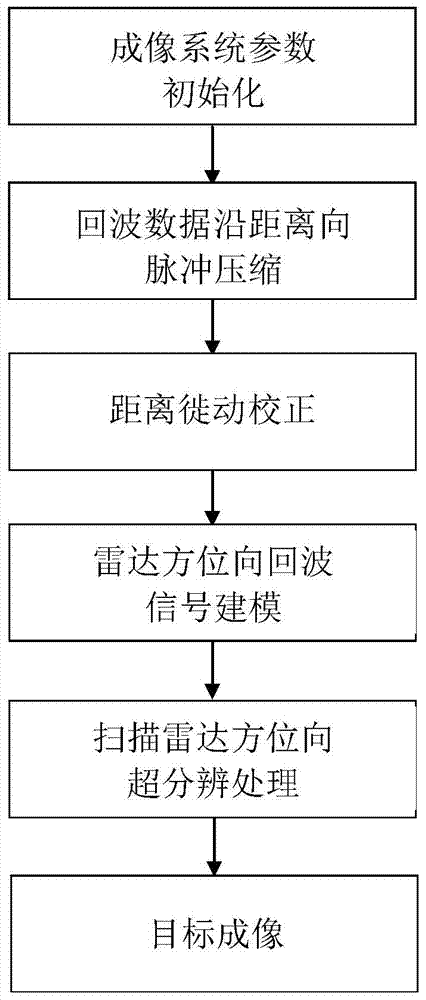
[0080] Step 1: Initialize the imaging system parameters

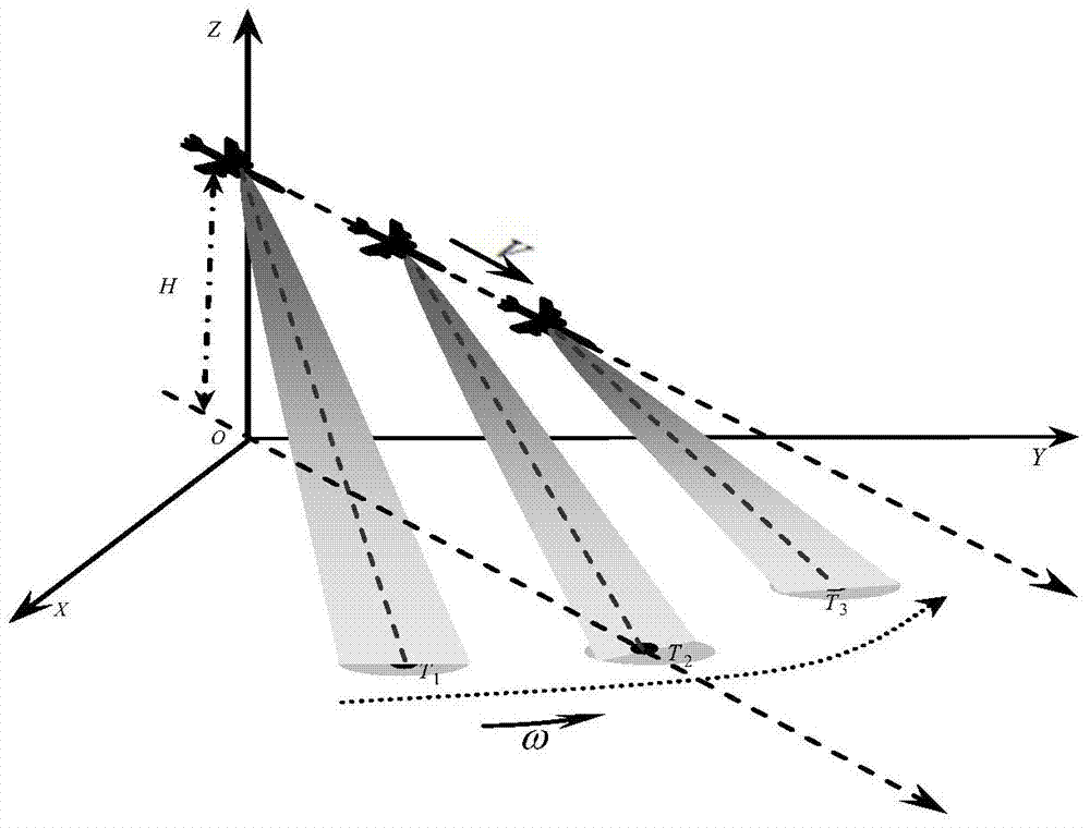
[0081] The imaging geometry mode used in this simulation verification is as follows figure 2 As shown, the system coordinate system takes the radar projected on the ground directly below as the top view coordinate origin, the radar platform moves along the X axis at a velocity of V, the radar antenna scans the area directly in front of the platform at an angular velocity of ω, and the Y axis is the tangent track Direction, Z is the direction perpendicular to the ground. The corresponding radar imaging system parameters are shown in Table 1.

[0082] Table 1

[0083]

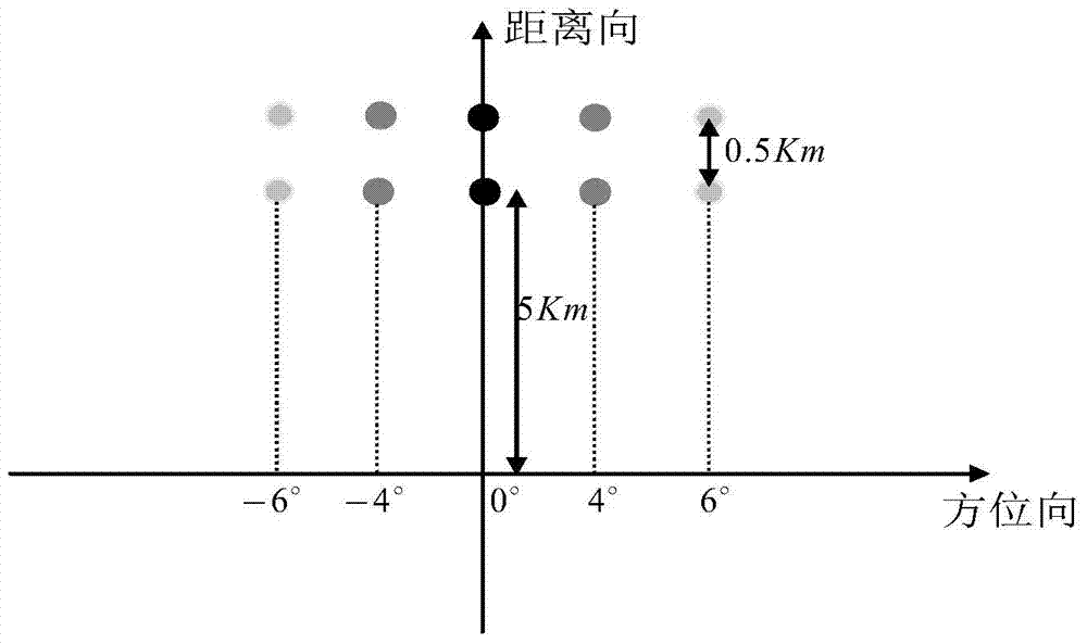
[0084] The imaging scene used in this example is image 3 As shown, the dots on the way are 2×5 point targets arranged on ...


PUM


Abstract

The invention discloses an airborne scanning radar imaging method in an iteration compression mode. The airborne scanning radar imaging method is characterized in that an azimuth-direction super-resolution imaging back model is built under the Bayesian theory framework, and the model built under the Bayesian theory can effectively fuse prior information of a target. When the super-resolution imaging back model is built, the assumption of a radar imaging basic idea on the noise statistical property is followed, and the Gaussian distribution function is adopted in the model to describe the noise statistical property. Due to the fact that target scattering has sparsity relative to an imaging background, the prior information of target scattering is described through the Laplace distribution function, radar super-resolution imaging is precisely converted into the maximum posterior probability problem in mathematics, corresponding target information when the posterior probability is maximum is solved, then the target information is reconstituted, and therefore the radar super-resolution imaging is achieved.

Description

Technical field [0001] The invention belongs to the field of radar technology, and specifically relates to airborne pulse Doppler radar forward-looking scanning imaging, helicopter radar circular scanning omnidirectional imaging, and spacecraft rendezvous interface scanning imaging. Background technique [0002] Radar can penetrate clouds and rain and is not restricted by the sun's rays. It has the ability to detect and search the ground and ocean all-weather and all-day. It can be used in military reconnaissance, terrain mapping, land / sea tracking and rescue, and maritime anti-smuggling. Indispensable and important role. [0003] Airborne scanning radar is to make the radar beam evenly scan the detected area in azimuth through mechanical rotation during the flight of the aircraft. Using the time relationship of the sequence of the radar antenna sweeping the target, through the effective processing of the echo data, the reflection information of the target in the space orientation...

Claims


Application Information

Patent Timeline
Patent Type & Authority Applications(China)
IPC IPC(8): G01S13/89
CPCG01S7/41G01S13/89
Inventor 黄钰林查月波张寅武俊杰蒋文杨建宇
Owner UNIV OF ELECTRONICS SCI & TECH OF CHINA
Why Eureka
Try Eureka