Folding reflector

A reflector and foldable technology, which is applied to reflectors, instruments, lighting devices, etc., can solve a lot of problems such as force, trouble and disadvantages of opening, and achieve the effect of flexible connection and easy implementation of opening

Active Publication Date: 2014-01-01
BRON ELEKTRONIK
View PDF7 Cites 2 Cited by
  • Summary
  • Abstract
  • Description
  • Claims
  • Application Information

AI Technical Summary

Problems solved by technology

The opening of the umbrella is usually laborious and requires a lot of force, which is particularly disadvantageous when the umbrella is large

Method used


Image

  • Folding reflector
  • Folding reflector
  • Folding reflector

Examples


Embodiment Construction

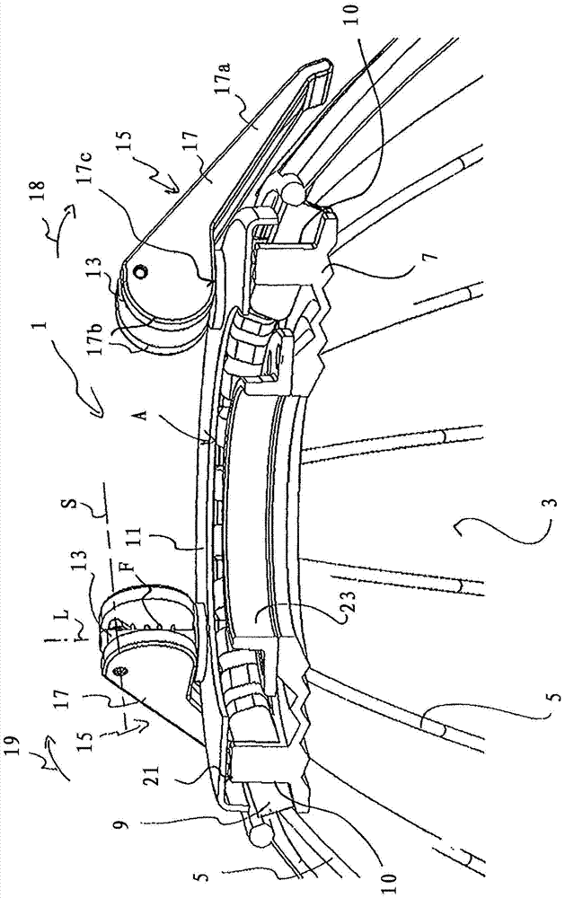
[0046] figure 1 Shows a perspective sectional view of a folding reflector 1 according to one embodiment of the invention in the unfolded state (expanded position), hereinafter also referred to simply as reflector. Described reflector 1 comprises reflective masking material 3, and reflective masking material can be stretched by means of umbrella spoke 5, and in order to umbrella spoke 5 is fixed on the reflective masking material 3, reflective masking material can have for example on its outer side To accommodate the flanging of the umbrella spokes 5. In principle, however, the umbrella spokes 5 can also be attached to the covering material 3 in other ways. In particular, fastening elements, in particular loops, preferably rubber loops, can also be provided on the inside of the covering material for fastening the umbrella spokes. The umbrella spokes 5 are articulated on a support body 7 designed here as a support ring and each have a section 9 protruding beyond the hinge at i...


PUM


Abstract

The invention relates to a folding reflector (1) having shade spokes (5) that are annularly hinged on a bearing body (7), by which spokes a reflecting cover (3) can be mounted. The reflector is characterized in that the ends of the shade spokes (5) that turned toward the linkage thereof extend beyond said linkage respectively and in that, due to the effect on said sections (9) of the shade spokes (5) extending beyond the linkage, said sections can be moved into the mounting position and back.

Description

technical field [0001] The invention relates to a folding reflector according to the preamble of claim 1 . Background technique [0002] A folding reflector of the type described here is known, for example, from DE 20 2004 001 528 U1. The reflector can be expanded in the shape of an umbrella and has on the support body a plurality of umbrella spokes articulated coronally, by means of which the reflective covering material can be expanded. The reflector serves in particular to reflect electromagnetic waves and especially light and / or sound waves. Such reflectors are used, for example, for lighting purposes when taking pictures. The reflector based on the umbrella structure with umbrella spokes can be folded for mobile use for transport purposes and can be unfolded at the point of use. The opening of the umbrella is generally complex and requires a lot of force, which is particularly disadvantageous with larger umbrellas. Contents of the invention [0003] It is therefor...

Claims


Application Information

Patent Timeline
Patent Type & Authority Applications(China)
IPC IPC(8): G03B15/06
CPCG03B2215/0525G03B15/06F21V7/18
Inventor F·波特曼
Owner BRON ELEKTRONIK
Why Eureka
Try Eureka