
Combospin Negative Pressure Air Concentration Mechanism

A combo spinning and air flow technology, applied in spinning machines, textiles and papermaking, drafting equipment, etc., can solve the problems of difficult cleaning of connectors, affecting production efficiency, large negative pressure loss, etc. The cleaning operation is convenient and the effect of reducing negative pressure loss

Active Publication Date: 2015-09-09
常州市同和纺织机械制造有限公司
View PDF8 Cites 0 Cited by
  • Summary
  • Abstract
  • Description
  • Claims
  • Application Information

AI Technical Summary

Problems solved by technology

However, when cleaning the accumulation mechanism of this structure, the flying flowers in the shell can only be easily cleaned through the negative pressure airflow, while the flying flowers in the connectors, especially the air cavity of the cover plate, are not easy to clean, and sometimes even need to be removed for cleaning, which will affect the production efficiency
Furthermore, since the air holes on the housing communicate with the air chambers on the connector through the air chambers on the cover plate, when the air chambers are connected, while changing the air flow direction, there is also the problem of air hole diameter reduction, resulting in Large air resistance, large negative pressure loss

Method used

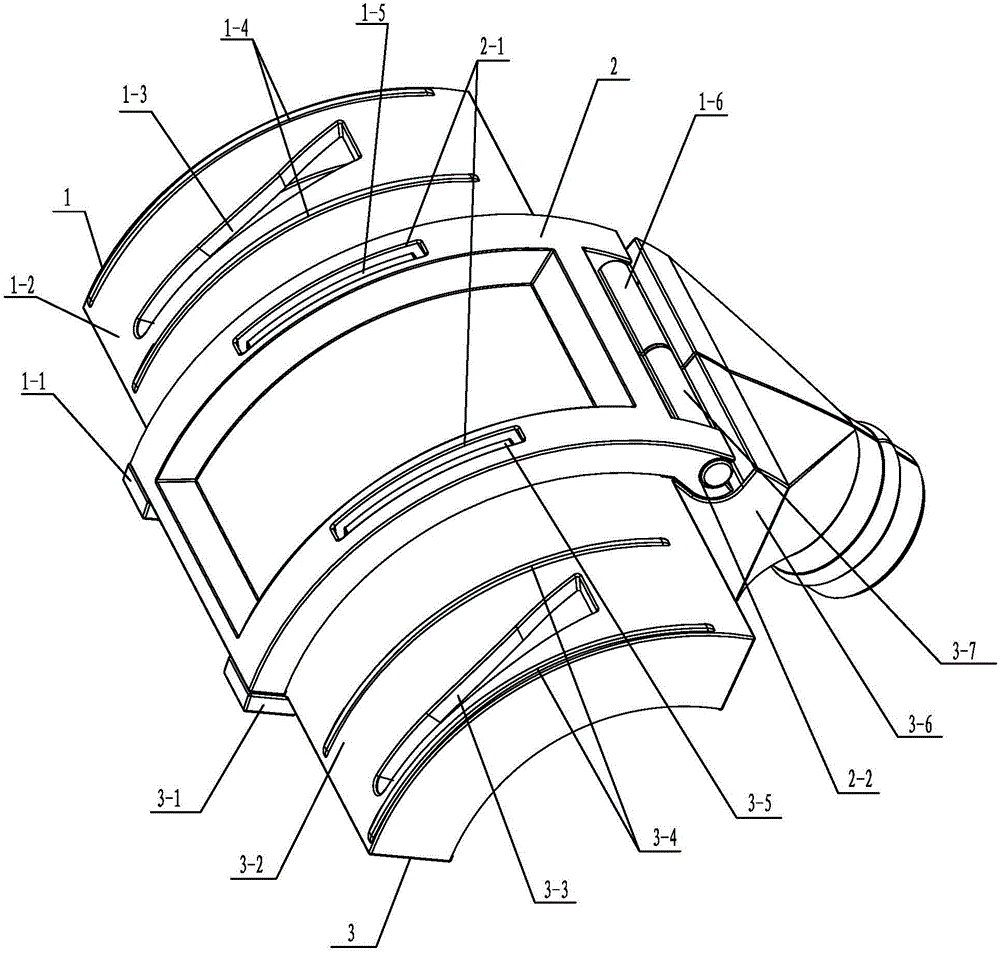
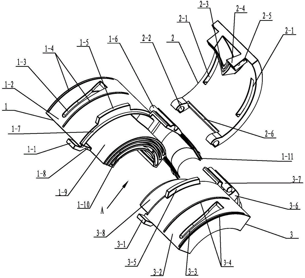
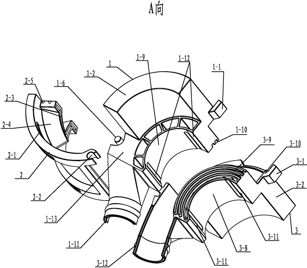

Image

  • Combospin Negative Pressure Air Concentration Mechanism
  • Combospin Negative Pressure Air Concentration Mechanism
  • Combospin Negative Pressure Air Concentration Mechanism

Examples


Embodiment Construction

[0013] See Figure 1~3 As shown, the Comforspin negative pressure air gathering mechanism of the present invention includes a left air gathering part 1 , a right air gathering part 3 and a cover plate 2 .

[0014] See Figure 1~3 As shown, the left air flow collection part 1 of the present invention includes an arc-shaped left base 1-9, a left cover 1-2 with an air cavity inside and a left cover 1-9 integrated with the left base 1-9, and the top of the left cover 1-2 There is a left collecting groove 1-3 communicating with the air cavity, and the right air flow collecting part 3 includes an arc-shaped right base 3-8 and a right cover body 3-8 with an air cavity inside which is integrated with the right base 3-8. 2. The top of the right cover body 3-2 is provided with a right accumulating groove 3-3 connected with the air cavity, and the left whisker sticks to the left accumulating groove 1-3 through the airflow in the air cavity of the left cover body 1-2 At the same time, t...


PUM


Abstract

The invention relates to a ComforSpin negative pressure airflow gathering mechanism. A left airflow gathering piece comprises an arc left base and a left cover body. An air cavity is arranged in the left cover body. A left gathering groove is formed in the top of the left cover body. A right airflow gathering piece comprises an arc right base and a right cover body. An air cavity is arranged in the right cover body. A right gathering groove is formed in the top of the right cover body. The left airflow gathering piece is in sealed connection with the right airflow gathering piece through a left concave-convex groove in the inner side face of the left base and a right concave-convex groove in the inner side face of the right base in an inserting mode. The back portion of the left cover body and the back portion of the right cover body are spliced to form a connecting pipe connector. Cover plates with front blocking plates are hinged to the left cover body and / or the right cover body. When the cover plates are arranged on the opening sides of the left cover body and the right cover body and on the left base and the right base in a covering mode, the cover plates are connected with the left airflow gathering piece and the right airflow gathering piece in a clamping mode. The cover plates, the air cavity on the left airflow gathering piece and the air cavity on the right airflow gathering piece form a channel which is needed by negative pressure airflow during gathering. The ComforSpin negative pressure airflow gathering mechanism has the advantages of being simple in structure, gathering effect is improved, the inner flying blocking phenomenon is avoided, and energy is saved.

Description

technical field [0001] The invention relates to a Comforspin negative-pressure airflow gathering mechanism, which belongs to the technical field of negative-pressure airflow gathering for compact spinning machines. Background technique [0002] In order to reduce the spinning triangle area of ​​the ring negative pressure compact spinning frame, a negative pressure airflow gathering device for gathering fiber strands is added downstream of the main drafting. The Comforspin negative pressure airflow gathering mechanism is in the gathering groove close to the inner surface of the mesh roller. The surface of the mesh roller at the position of the airflow guide groove of the compressed airflow mechanism is gathered, thereby effectively reducing the spinning triangle area, achieving the purpose of reducing yarn hairiness and increasing yarn tension. For this reason, the Kamospin negative pressure airflow gathering device puts forward the following requirements for the negative pr...

Claims


Application Information

Patent Timeline
Patent Type & Authority Patents(China)
IPC IPC(8): D01H5/72
Inventor 屈臻辉顾鸿奎高菁芸滕彬
Owner 常州市同和纺织机械制造有限公司
Learn More