Glass block dichroic beamsplitters

a dichroic beam and glass block technology, applied in the field of dichroic beam splitters, can solve the problems of increased spherical aberration as well as appreciable asymmetric aberration, high angle of light incidence, and is not desirable or possible to tolerate a lateral shift of image-bearing light beams. , to achieve the effect of improving spectral performance and low aberration and beam shi

Active Publication Date: 2013-11-21
IDEX HEALTH & SCI
View PDF2 Cites 17 Cited by
  • Summary
  • Abstract
  • Description
  • Claims
  • Application Information

AI Technical Summary

Benefits of technology

[0015]Therefore, there is a need for a dichroic beamsplitter cube that supports orthogonal input and output light paths, that takes advantage of the low aberration and beam shift of

Problems solved by technology

If this light is not collimated, however, the tilted parallel plate of glass on which the thin-film coating is formed causes increased spherical aberration as well as appreciable asymmetric aberrations, such as coma and astigmatism, at the image.
In some systems it is not desirable or possible to tolerate a lateral shift of the beam of image-bearing light, and therefore, of the optical axis, as caused by the tilted parallel plate.
One notable drawback of the cube approach, however, relates to high angles of light incidence on the embedded multilayer thin-film coating 124 that lies within the prism.
It is well-known that filter response for thin film filters changes with angle, so that multilayer thin film coatings tend to degrade in performance as the angle of incidence increases.
It is much more difficult to design and fabricate a dichroic beamsplitter coating with a steep, well-defined edge transition between reflection and transmission for light incident

Method used


Image

  • Glass block dichroic beamsplitters
  • Glass block dichroic beamsplitters
  • Glass block dichroic beamsplitters

Examples


Embodiment Construction

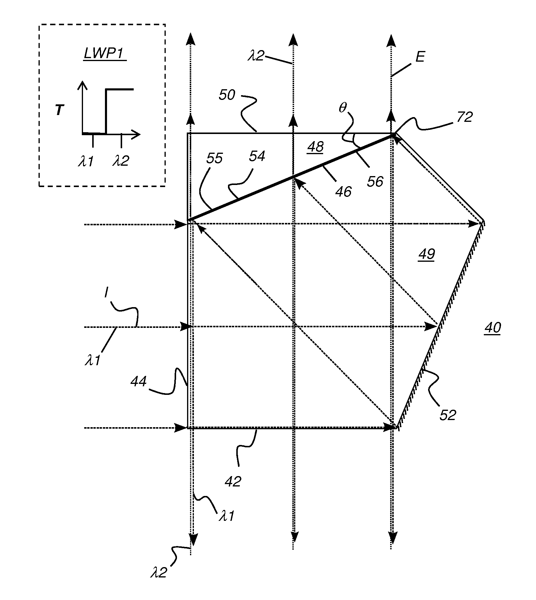
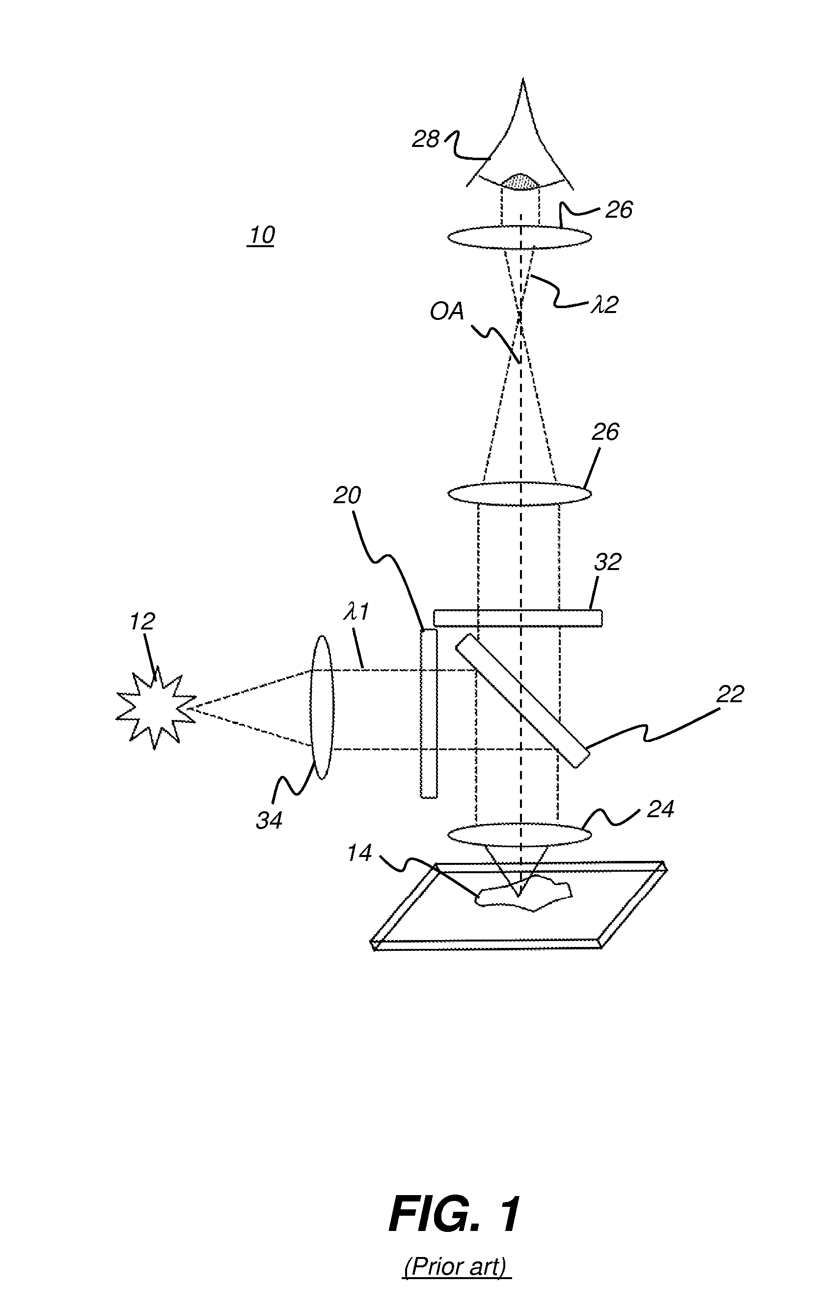
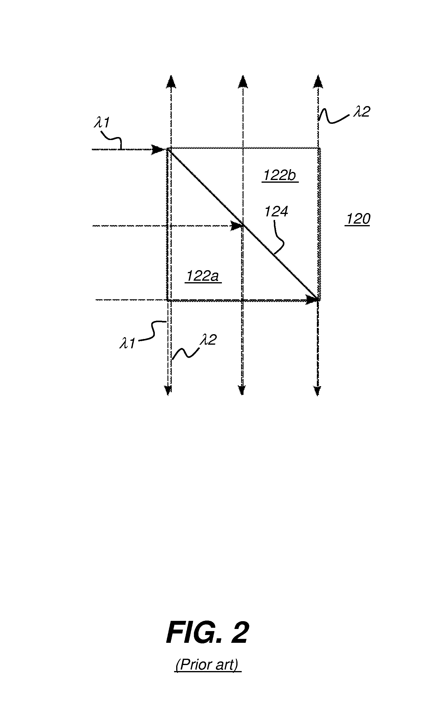
[0043]The present description is directed in particular to elements forming part of, or cooperating more directly with, apparatus in accordance with the invention. It is to be understood that elements not specifically shown or described may take various forms well known to those skilled in the art.

[0044]Figures shown and described herein are provided in order to illustrate key principles of operation and component relationships along their respective optical paths according to the present invention and are not drawn with intent to show actual size or scale. Some exaggeration may be necessary in order to more clearly emphasize basic structural relationships or principles of operation. In addition, some of the figures provided may, for the sake of clarity, show space between components that are actually in optical contact in the claimed apparatus.

[0045]Where they are used, the terms “first”, “second”, “third”, and so on, do not necessarily denote any ordinal or priority relation, but ...


PUM


Abstract

A dichroic beamsplitter has a composite prism that has at least first and second prism elements that are coupled together along facing surfaces, wherein the respective facing surfaces of the first and second prism elements are equidistant from each other. The composite prism has a first flat external surface that lies within a first plane, a second flat external surface that lies within a second plane that is perpendicular to the first plane, a third flat external surface that lies within a third plane that is parallel to the second plane, and a coated surface internal to the composite prism and having a multilayer thin-film dichroic beamsplitter coating, wherein the coated surface lies within a fourth plane that intersects at least one of the first, second, and third planes at an angle that is less than about 25 degrees.

Description

CROSS-REFERENCE TO RELATED APPLICATIONS[0001]This application claims the benefit of U.S. Provisional Patent Application Ser. No. 61 / 648,242 filed May 17, 2012 in the names of Turan Erdogan et al., the contents of which are incorporated fully herein by reference.FIELD OF THE INVENTION[0002]This invention generally relates to apparatus and methods for separation of light paths according to spectral content and more particularly relates to dichroic beamsplitter prisms.BACKGROUND OF THE INVENTION[0003]Optical beamsplitters are used in a number of different applications. In spectroscopy and other instrumentation systems, for example, a beamsplitter is used to direct excitation energy of one wavelength toward a sample along a first optical path and to direct emitted light that has been excited from the sample to sensing components along a second optical path, which can be in the opposite direction from some portion of the first optical path. The beamsplitter reflects light of at least one...

Claims


Application Information

Patent Timeline
IPC IPC(8): G02B27/12
CPCG02B27/126G02B27/1006G02B27/142G02B27/149
Inventor ERDOGAN, TURANWANG, LIGANGPRABHAT, PRASHANT
Owner IDEX HEALTH & SCI
Why Eureka
Try Eureka