Wide-angle projection optical system

a projection optical system and wide-angle technology, applied in the field of projection optical systems, can solve the problems of difficult to have a thin projection optical system, projection display apparatus, and potential dangers of illumination of the eyes of lecturer, and achieve the effect of removing the drawbacks of conventional optical systems

Active Publication Date: 2016-09-22
DELTA ELECTRONICS INC
View PDF8 Cites 6 Cited by
  • Summary
  • Abstract
  • Description
  • Claims
  • Application Information

AI Technical Summary

Benefits of technology

[0009]It is an aspect of the present invention to provide a wide-angle projection optical system with short-throw in order to eliminate the drawbacks of dangers of a conventional optical system, distortions and aberrations.
[0010]An another aspect of the present invention provides a wide-angle projection optical system with ultra-short-throw having a large full field angle, which is for example larger than 70 degrees, a short effective focal length, thin profile, low distortion and aberration and high image quality.

Problems solved by technology

In addition, the eyes of the lecturer have the potential danger of being illuminated by the light from the projection display apparatus 10.
This makes it difficult to have a thin projector system.
However, the optical components of the wide-angle projection optical system have to be tilted and decentered in arrangement for obtaining an undistorted image with better image quality.
Otherwise, optical components having anamorphic polynomial free-form surfaces with different magnifications in vertical direction and horizontal direction are necessary to be used in the wide-angle projection optical system, and the complication of assembling or manufacturing optical components are increased.

Method used


Image

  • Wide-angle projection optical system
  • Wide-angle projection optical system
  • Wide-angle projection optical system

Examples


Embodiment Construction

[0035]The present disclosure will now be described more specifically with reference to the following embodiments. It is to be noted that the following descriptions of preferred embodiments of this disclosure are presented herein for purpose of illustration and description only. It is not intended to be exhaustive or to be limited to the precise form disclosed.

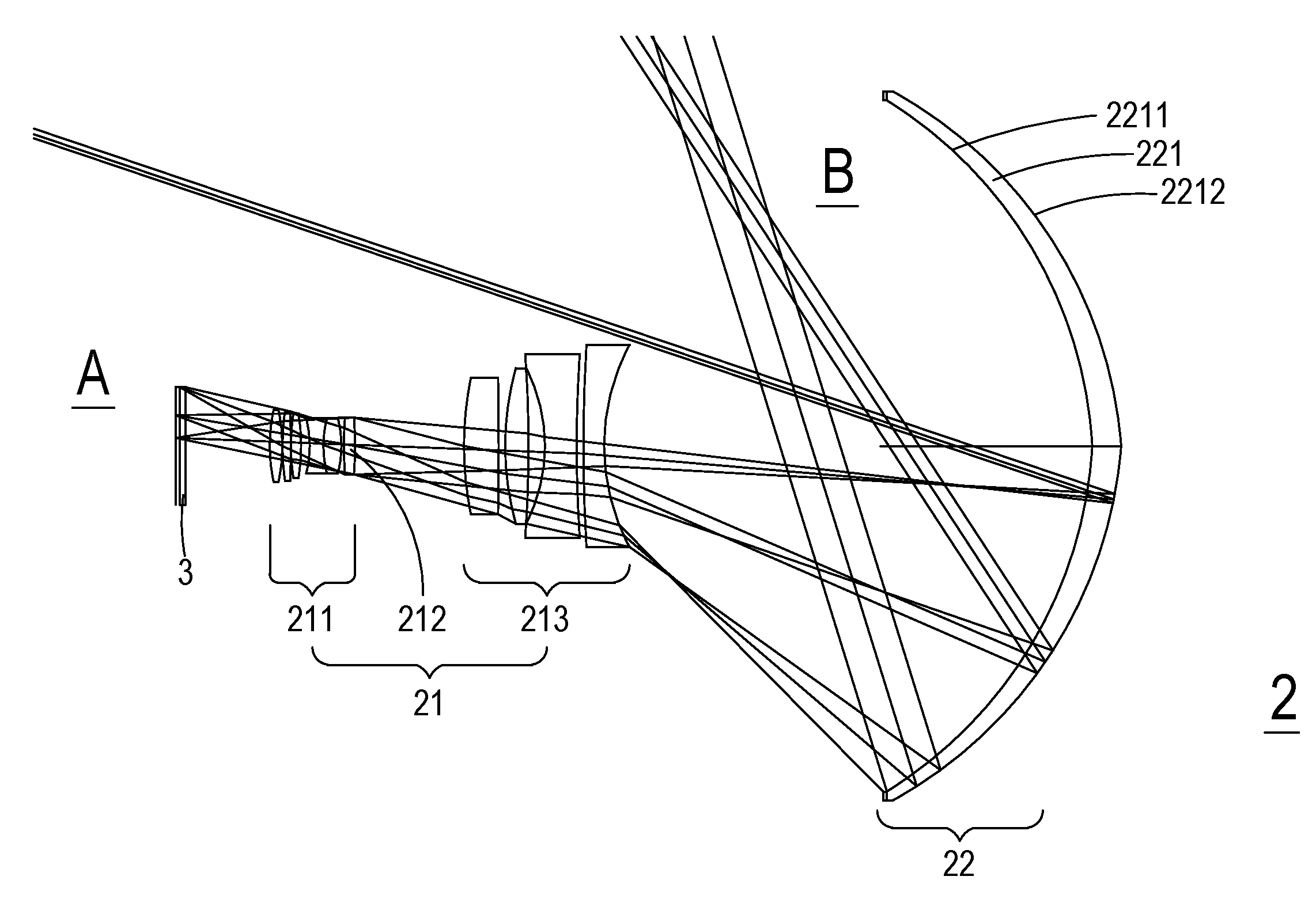
[0036]Please refer to FIG. 2. FIG. 2 is a schematic diagram illustrating the configuration of a wide-angle projection optical system according to an embodiment of the present invention. As shown in FIG. 2, the wide-angle projection optical system 2 is a non-telecentric projection optical system, which can be applied to a projection display apparatus. The projection display apparatus includes, but not limited to, a digital micromirror device (hereinafter “DMD”). The DMD has an object surface 3, which is an image-displaying surface of a light valve. The object surface 3 is configured as an object side A for the image projected by...


PUM


Abstract

A wide-angle projection optical system includes, between an object side and an image side, a first optical system including a first lens group having an aperture stop and a second lens group disposed behind the aperture stop, and a second optical system including a Mangin mirror and a glass plate disposed between the second lens group and the Mangin mirror. The first and second lens groups have positive power. The first lens group provides optical characteristics to match with a light coming from the object side. The first and second lens groups are configured to form an aberrated real image. The Mangin mirror is disposed closer to the image side than others. The Mangin mirror includes a refracting surface and a reflecting surface for refracting the light two times and reflecting the light one time, thereby producing an enlarged real image on a screen. Therefore, the image quality is enhanced.

Description

CROSS-REFERENCE TO RELATED APPLICATION[0001]This application is a continuation-in-part application of U.S. application Ser. No. 14 / 167,782 filed on Jan. 29, 2014, which claims the benefit of priority of Taiwan Application No. 102144713 filed on Dec. 5, 2013, the entirety of which is hereby incorporated by reference.TECHNICAL FIELD[0002]The present disclosure relates to a projection optical system, and more particularly to an ultra-short-throw or a wide-angle projection optical system.BACKGROUND[0003]A wide-angle projection lens has a large field of view, or a short effective focal length (EFL). In comparison with a conventional projection lens, the projection display apparatus with a wide-angle projection lens is capable of producing a certain sized image at a shorter distance.[0004]Recently, an integrated system of a projection display apparatus and an interactive white board has become very useful tool in classrooms, lecture rooms or conference rooms in order to provide the intera...

Claims


Application Information

Patent Timeline
Patent Type & Authority Applications(United States)
IPC IPC(8): G02B17/08G02B13/18G03B21/28G02B13/16G02B27/00
CPCG02B17/0856G02B13/16G02B13/18G03B21/28G02B27/0025G02B13/04G02B13/22
Inventor LIN, LAI CHANG
Owner DELTA ELECTRONICS INC
Why Eureka
Try Eureka