Seabed located storage

a technology of located storage and seabed oil, which is applied in the direction of transportation and packaging, service pipe systems, and well accessories, etc., can solve the problems of significant reduction of load value, unusable emulsion layer in oil load, and sulphuric acid, and achieve the effect of easing the unloading of oil

Active Publication Date: 2008-11-11
NOV PROCESS & FLOW TECH AS
View PDF7 Cites 38 Cited by
  • Summary
  • Abstract
  • Description
  • Claims
  • Application Information

AI Technical Summary

Benefits of technology

[0021]With the storage according to the present invention full separation of oil and water is achieved, such that formation of an emulsion layer is avoided and the danger of bacterial growth (SRB) is eliminated. Further, a large degree of flexibility is achieved, which means that the storage can be connected to any type of oil production plant, it can easily be placed and moved to new fields, and the storage is independent of water depths within the depths for which oil production presently and in foreseeable future takes place. The water pressure around the storage helps to give a uniform filling and effective unloading of the storage. The storage can relatively easy be taken up and materials be recirculated to other purposes after expiry of the life period. The storage according to the invention can also be used for gas storage in addition to storage of different liquids, with adaptation of the construction to handle the increased buoyancy.

Problems solved by technology

In connection with storage in the above-mentioned way an undesirable emulsion layer will be formed in the oil load, including oil, water and chemicals.
Further, the ingress of relatively small amounts of seawater into the oil load results in undesired salt contents and thereby significantly reduced value of the load.
With a water-oil-storage of the above-mentioned type a usual problem is undesired bacterial growth (termed SRB), which in combination with water results in sulphuric acid.
It is known that said bacterial growth has resulted in severe problems for tank and pipe systems both on platforms and buoy loading tankers.
Said separation and rendering harmless of hazardous components are very expensive and only very few refineries or others undertake such jobs.

Method used


Image

  • Seabed located storage
  • Seabed located storage
  • Seabed located storage

Examples


Embodiment Construction

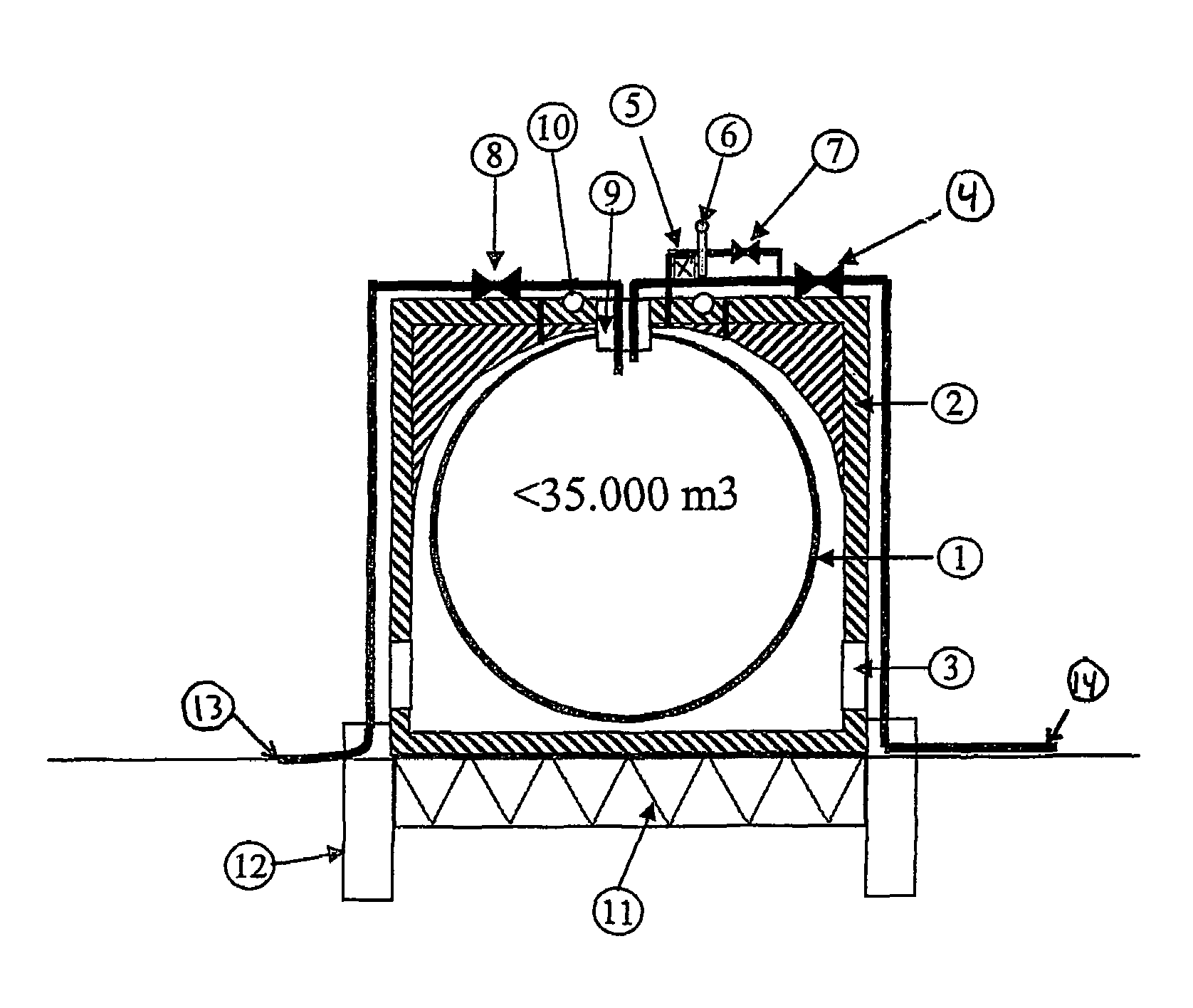
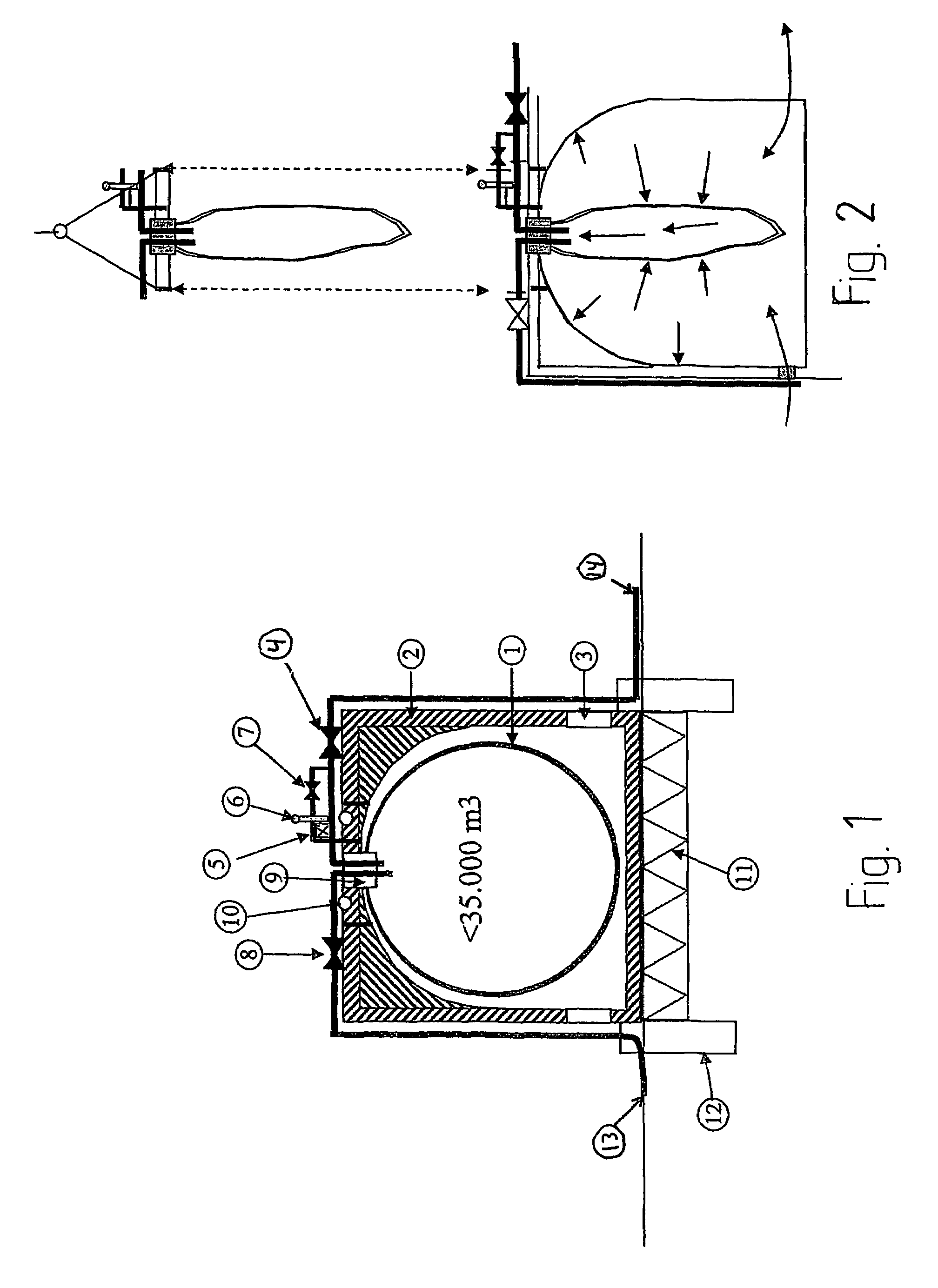
[0027]Reference is first made to FIG. 1 illustrating the storage according to the invention. More specific a storage 1 of oil- and waterproof flexible material is illustrated. Further, a structure section 2 is illustrated, which can be made from ferroconcrete, steel or other feasible construction material. Openings 3 for free passage of seawater are provided in the lower part of the structure section. Arranged is a remotely controllable valve 4 between the storage section and the unloading line. In connection to a pipe that is extending between the upper part of the structure section and the unloading pipe it is arranged a remotely controllable valve 7, an oleometer 5 for registration of oil contents between the storage section and the upper part of the structure section, in addition to a transponder 6 for alarm to the platform or optionally to a buoy loading ship at oil leakage. With said pipe leaked out oil can be brought into the unloading pipe with a dedicated pump (not illustra...


PUM


Abstract

Seabed located storage for crude oil or other fluid, distinguished in that it is comprising a storage section in form of an oil and waterproof cloth formed as a flexible balloon that can be filled with, store and emptied for a storage fluid, a structure section formed as an external casing over the storage section, which structure section is closed in the upper part such that an upward close volume of size at least corresponding to the volume of the storage section is formed, but with openings to the surroundings in the lower part, an anchoring section formed as a substructure between the structure section and the seabed, with means for anchoring to or stable placement on the seabed, and a transfer section comprising pipes and valves for loading and unloading of a storage fluid, arranged in substance exterior to the upper part of the storage.

Description

FIELD OF THE INVENTION[0001]The present invention regards storage at sea of crude oil or other fluid. The invention regards in particular seabed located storage of stabilized crude oil.[0002]The invention is in particular useful in connection with marginal oil fields for which the expenses for a separate pipeline to shore or to another installation cannot be justified or oil fields in their end period of operation, for which costs to investments and maintenance are to be kept at low level. The invention is also beneficial with respect to oil fields for which it is desirable with continuous production and delivery of produced crude oil, and for which it is desirable with a stockpile, for example during temporary shut down of an existing pipe system for delivery of the produced crude oil.PRIOR ART AND BACKGROUND OF THE INVENTION[0003]Storage of crude oil at sea at present usually takes place at sea surface, on floating storage vessels, in loading buoys with storage capacity, or on the...

Claims


Application Information

Patent Timeline
Patent Type & Authority Patents(United States)
IPC IPC(8): B65D88/78
CPCB65D88/78E21B41/0007E21B43/36Y10T137/402
Inventor SAMUELSEN, ARILDBREIVIK, KARERAVNDAL, OLA
Owner NOV PROCESS & FLOW TECH AS
Why Eureka
Try Eureka