Quick torque coupling

a torque coupling and torque technology, applied in the direction of rod connection, mechanical equipment, manufacturing tools, etc., can solve the problems of btc-type design, unsuitable for true kinematic applications, misalignment of the positioning apparatus as a whole, etc., and achieve the effect of high reliability and suitable for fail-safe applications

Inactive Publication Date: 2006-08-03
LUFT PETER A
View PDF16 Cites 37 Cited by
  • Summary
  • Abstract
  • Description
  • Claims
  • Application Information

AI Technical Summary

Benefits of technology

[0018] First, the QTC eliminates vague and indeterminate conditions of intermediate assembly, such that the assembled condition falls simply into two distinct categories—it is either locked or unlocked. This eliminates the danger of a faulty assembled condition that might fail and / or cause the parent positioning apparatus to be misaligned. Therefore, assembly of the invention is highly reliable and suitable for fail-safe applications, which is an object and advantage.

Problems solved by technology

In fact, for reasons of practicality the latter are deliberately designed to accommodate misalignment, rendering them unsuitable for true kinematic applications.
The BTC-type design presents several problems in certain applications involving a positioning apparatus.
Also, this mis-assembly will cause the positioning apparatus as a whole to be mis-aligned.
As mentioned, it cannot be readily determined by visual inspection whether a BTC-type coupling has been incorrectly assembled in this manner.
Therefore it is problematic to validate an assembly with many couplings, e.g. a field application.
Therefore the BTC and similar designs are unreliable in fail-safe applications, i.e. applications in which failure would be a high-consequence event.
Second, an external wrench is required to assemble a BTC-type coupling.
This tool can be misplaced or lost, rendering emergency assembly or disassembly problematic.
Worse, in an installation where loose items can cause catastrophic damage by falling into sensitive equipment, an external wrench requires tethering, which can complicate assembly.
Furthermore, an external wrench may be difficult to use in environments where the apparatus must be assembled in difficult or hostile environments requiring a technician to wear gloves.
Also, an external wrench in the hands of an assembly technician yields unpredictable results in terms of the tightened condition of a BTC-type nut unless a torque wrench is used, but the latter would be quite cumbersome and would require the concurrent use of a dedicated workstation to hold and secure the coupling during tightening.
Third, even when correctly assembled, it is not possible to determine by visual inspection whether a BTC-type nut has been properly tightened or is in fact loose, a condition that also renders failsafe operation problematic.
The reliance on friction, springs or clamping as an attachment scheme is fundamentally unreliable in environments requiring immersion in highly viscous (and therefore lubricating) fluids, such as encountered in a certain class of underground neutrino detectors.
Also, friction-based attachments schemes are undermined by vibration, regular or intermittent, e.g. shocks induced by dropping, etc.
However, these extra parts add complexity, and therefore increase installation difficulty, including the risk of lost parts, or of parts dropped into peripheral instrumentation, possibly resulting in catastrophic damage.
Fifth, the BTC-type threaded nuts are bulky in order to incorporate a set of female threads, as well as to have sufficient structural integrity to withstand assembly wrenching forces.
This bulk increases the overall weight of an assembly.
Sixth, assembly of a threaded BTC-type nut assembly is time-consuming, because the thread engagement must be carefully started and then turned several times, a wrench must be used, and the wrench force must be gauged somehow, possibly requiring the use of a dedicated assembly workstation and torque wrench.
Sixth, because the QTC is straightforward, simple, and requires no tools, it is therefore relatively rapid to assemble, compared to the prior art.

Method used


Image

  • Quick torque coupling
  • Quick torque coupling
  • Quick torque coupling

Examples


Embodiment Construction

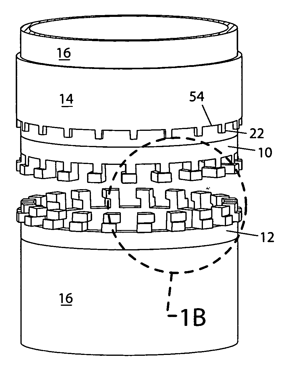
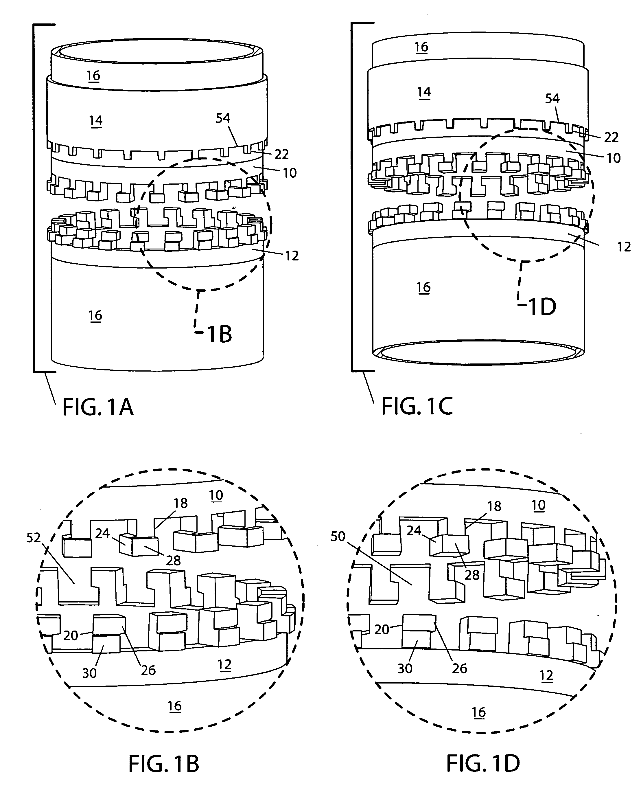
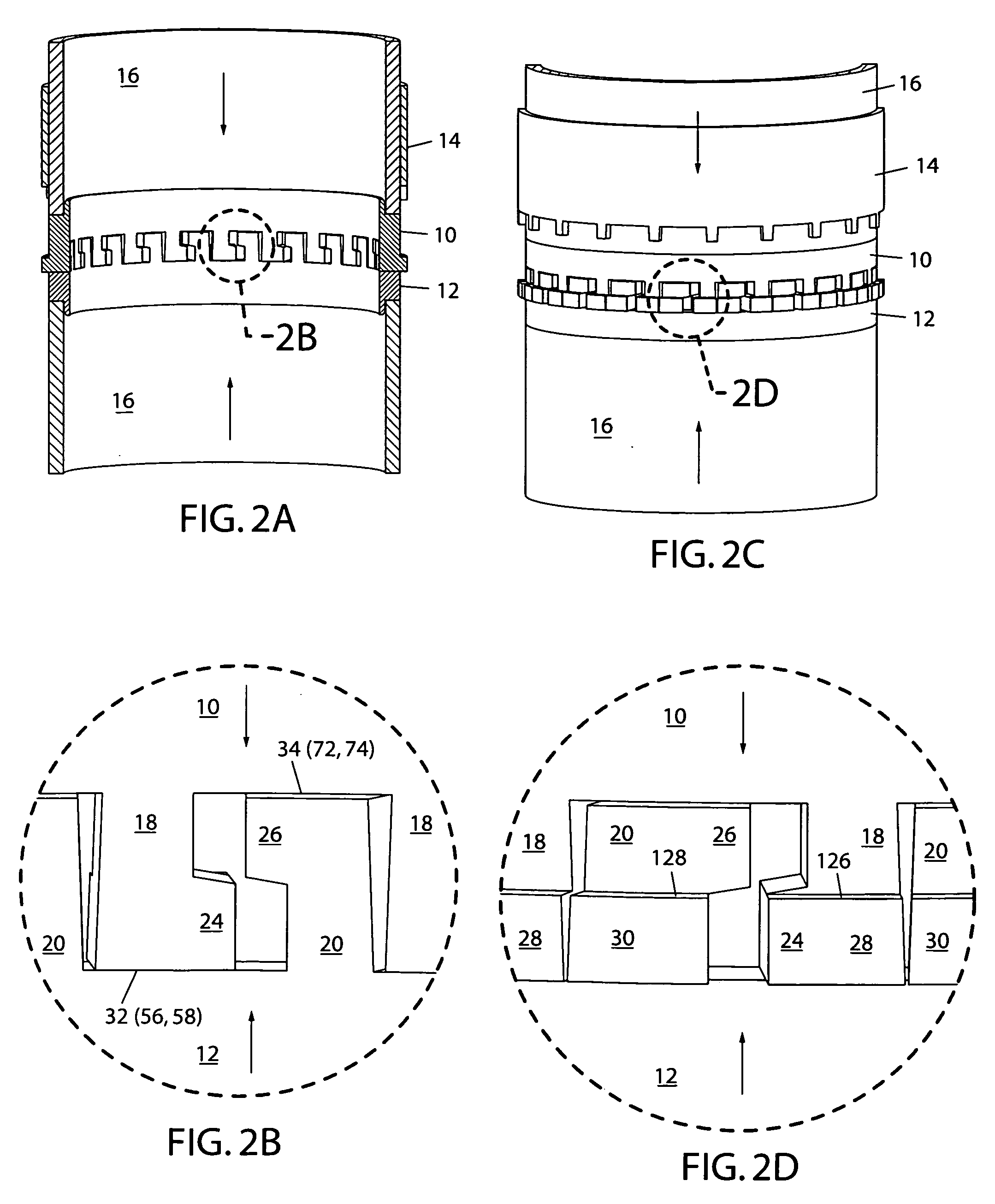
[0120] A preferred embodiment of the present invention is illustrated in FIGS. 1A and 1C, wherein both figures show the disassembled (unlocked) condition of the invention. Two steel or aluminum rings 10 and 12, each with a circumferential array of teeth 18 and 20 respectively, are welded or brazed to the ends of struts 16 such that their teeth extend axially outward. Other materials and / or joining techniques may be used instead. A locking ring 14 is assembled such that it slides over ring 10 with its teeth facing teeth 10. Ring 14 has a set of teeth 22, which engage the teeth 18 and 20 of rings 10 and 12 in the assembled condition. In the embodiment shown, the diameter of the struts 16 is about 3 inches. The wall thickness of the struts is about 1 / 16 inch, as is that of the ring 14. The teeth 18 and 20, of rings 10 and 12 have radial thickness that varies, but are not diametrically solid.

[0121] Although rings 10 and 12 each have a set of interlocking teeth 18 and 20 respectively, e...


PUM


Abstract

A coupling for mechanically connecting modular tubular struts of a positioning apparatus or space frame, comprising a pair of toothed rings (10, 12) attached to separate strut members (16), the teeth (18, 20) of the primary rings (10, 12) mechanically interlocking in both an axial and circumferential manner, and a third part comprising a sliding, toothed collar (14) the teeth (22) of which interlock the teeth (18, 20) of the primary rings (10, 12), preventing them from disengaging, and completely locking the assembly together. A secondary mechanism provides a nesting force for the collar, and/or retains it. The coupling is self-contained and requires no external tools for installation, and can be assembled with gloved hands in demanding environments. No gauging or measured torque is required for assembly. The assembly can easily be visually inspected to determine a “go” or “no-go” status. The coupling is compact and relatively light-weight. Because of it's triply interlocking teeth, the connection is rigid. The connection does not primarily rely on clamps, springs or friction based fasteners, and is therefore reliable in fail-safe applications.

Description

CROSS-REFERENCE TO RELATED APPLICATIONS [0001] This application claims the benefit of U.S. Provisional Patent Application No. 60 / 643,617, which was filed Jan. 12, 2005.FEDERALLY SPONSORED RESEARCH [0002] The United States government has rights in this invention pursuant to Contract No. DE-AC03-76SF00098 between the United States Department of Energy and the University of California, for the operation of Lawrence Berkeley National Laboratory.BACKGROUND OF THE INVENTION [0003] This invention relates to the mechanical connection of modular structural elements, such as those of a positioning apparatus or space frame. More particularly, the invention relates to the design of disconnectable couplings functioning as a means to this end. [0004] In the context of designing a positioning apparatus, the need arises to design structural elements of same that are rigid, therefore permitting accuracy of placement. Such an apparatus must also transmit mechanical power in order to execute placement...

Claims


Application Information

Patent Timeline
Patent Type & Authority Applications(United States)
IPC IPC(8): F16B12/04
CPCE04B1/5843F16B7/0406Y10S285/913F16B21/10Y10T403/472F16B21/04
Inventor LUFT, PETER A.
Owner LUFT PETER A
Why Eureka
Try Eureka