Opening-closing mechanism with self-locking devices

A technology of an opening and closing mechanism and a self-locking device, which is applied to the control mechanism, power control mechanism, locomotive and other directions of the wing fan, can solve the problems of high cost and complex structure, and achieve the effects of convenient maintenance, simple manual locking and simplified structure.

Active Publication Date: 2014-01-15
CRRC QINGDAO SIFANG ROLLING STOCK RES INST
View PDF6 Cites 45 Cited by
  • Summary
  • Abstract
  • Description
  • Claims
  • Application Information

AI Technical Summary

Problems solved by technology

[0004] The present invention aims at the above-mentioned disadvantages of the opening and closing mechanism at the front end of the high-speed EMU of the existing railway vehicles, such as complex structure and high cost, and provides an opening and closing mechanism with a self-locking device with a simple and reliable structure, convenient maintenance and low cost

Method used


Image

  • Opening-closing mechanism with self-locking devices
  • Opening-closing mechanism with self-locking devices
  • Opening-closing mechanism with self-locking devices

Examples


specific Embodiment 1

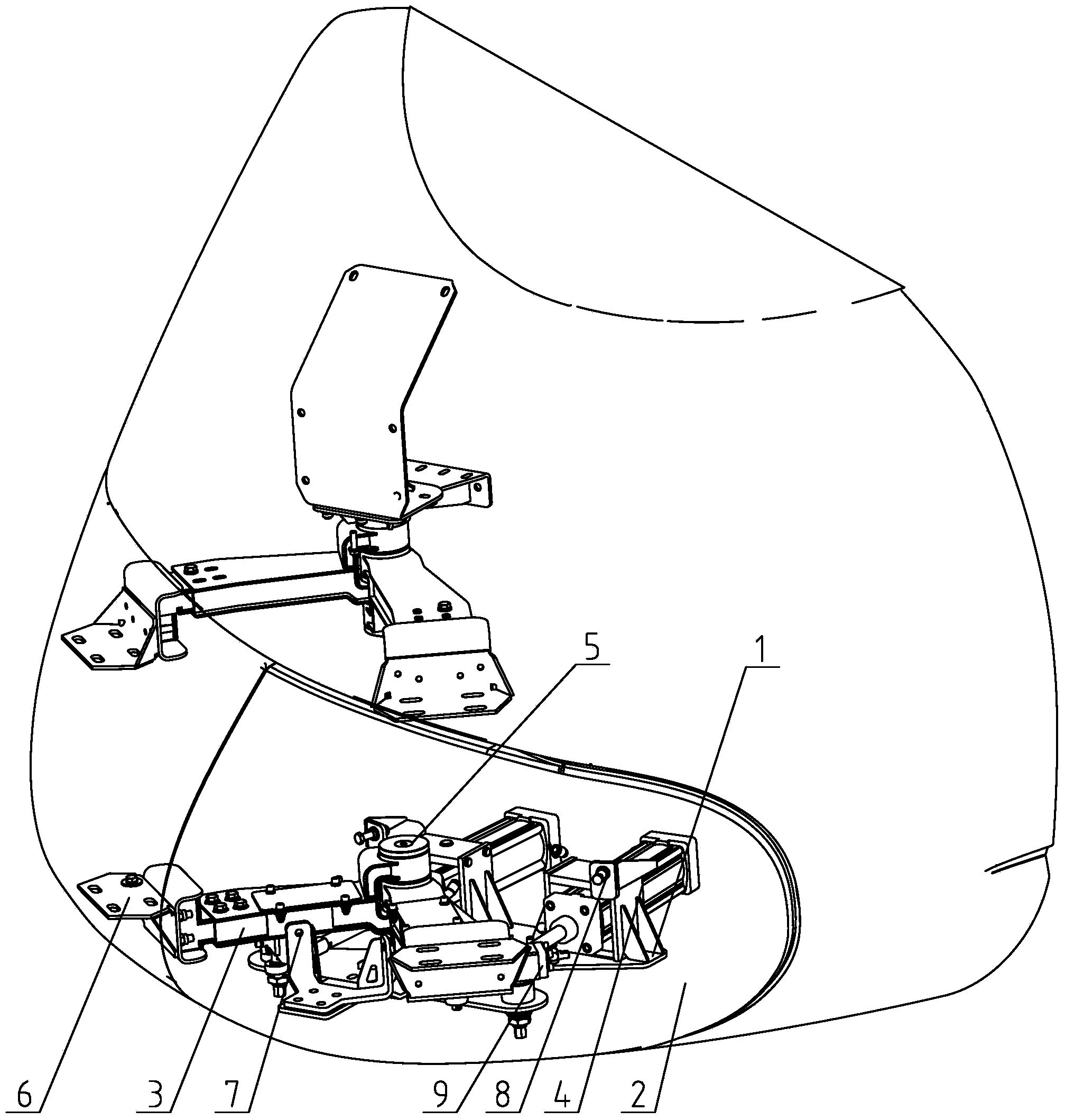
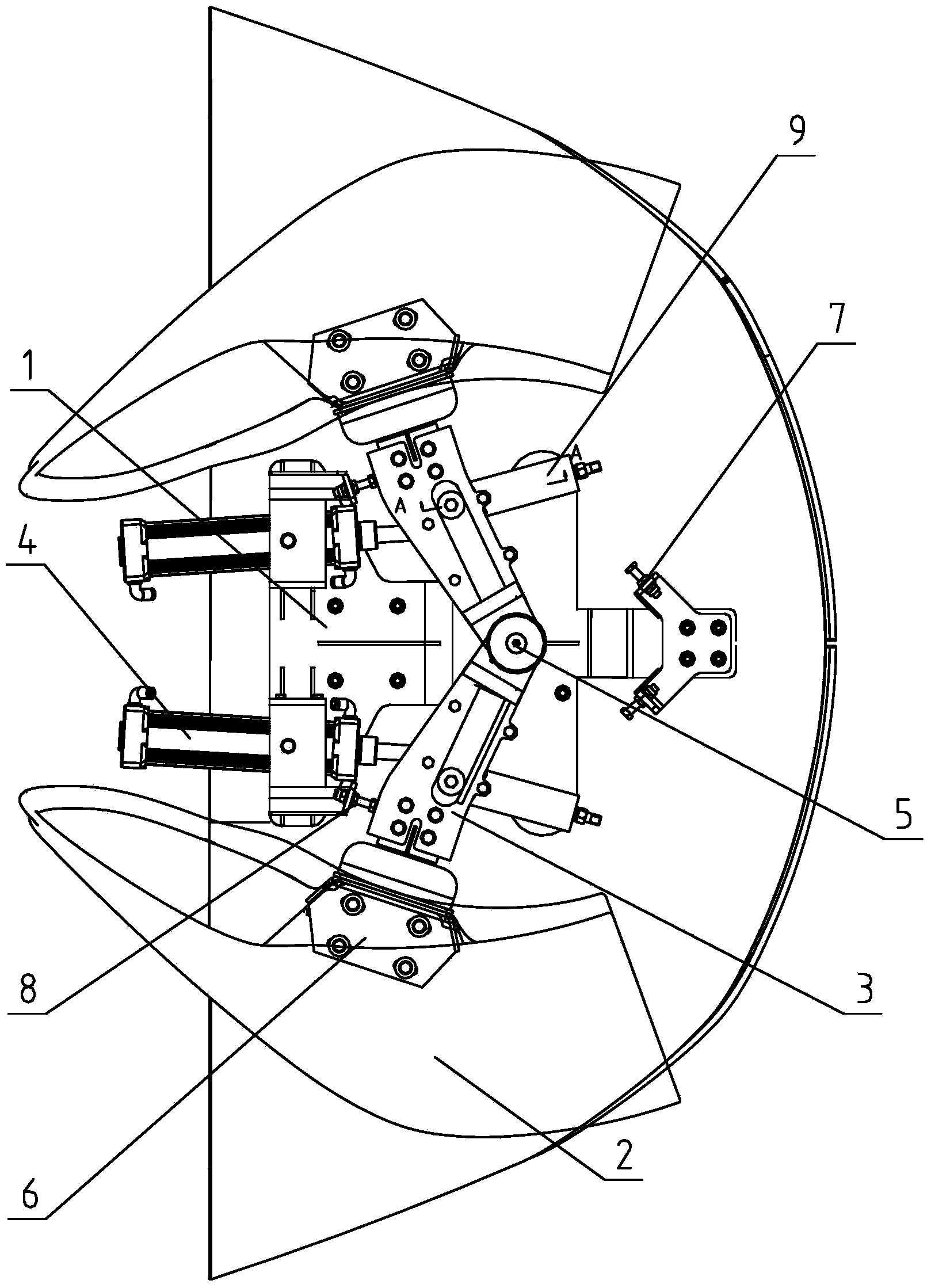
[0018] Specific embodiment one: as Figures 1 to 4 As shown, an opening and closing mechanism with a self-locking device, the opening and closing mechanism includes a bottom plate 1, a fairing 2, a fairing support arm 3 and a power source pushing cylinder 4, a rotating shaft 5 is arranged on the bottom plate 1, and the fairing supports One end of the arm 3 is set on the rotating shaft 5, and the other end is connected with the fairing 2 through the fairing mounting seat 6; An open state limit stopper 8 is arranged between them; a locking device 9 is arranged between the cowling support arm 3 and the power source pushing cylinder 4, and one end of the locking device 9 can move in the chute of the cowling support arm 3, and the other One end is installed on the power source pushing cylinder 4. During the opening or closing process of the opening and closing mechanism, the locking device 9 moves to form a mechanism dead point with the fairing support arm 3. When locking, the lock...

specific Embodiment 2

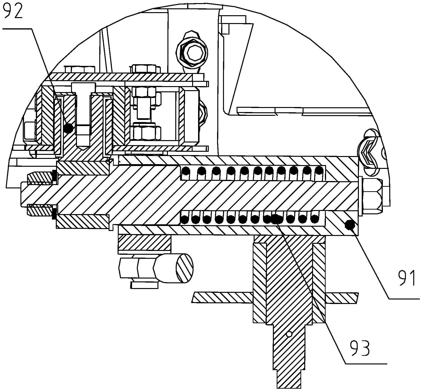
[0024] Specific embodiment two: different from specific embodiment one, in specific embodiment two, in order to realize the rolling connection between the locking device 9 and the fairing support arm 3, and play a self-locking role, the locking device 9 includes a cylinder 91 , the cylinder body 91 is preloaded with a roller device 92 and a spring 93, and one end of the cylinder body preloaded with the roller device is rollingly connected with the fairing support arm through the roller device, and the roller device can roll in the fairing support arm, and the roller of the roller device The bottom is connected with the power source push cylinder.

specific Embodiment 3

[0025] Specific embodiment 3: different from specific embodiment 1, in specific embodiment 3, there are two rotating shafts 5 located on both sides of the bottom plate 1, and the two rotating shafts 5 are respectively fitted with the fairing support arms 3 on the same side One end of the fairing support arm 3 is connected with the fairing 2 through the fairing mounting seat 6 .


PUM


Abstract

The invention relates to an opening-closing mechanism with self-locking devices. The opening-closing mechanism comprises a base plate, a fairing, fairing supporting arms and power source pushing air cylinders. A rotary shaft is arranged on the base plate, one ends of the fairing supporting arms are installed on the rotary shaft in a sleeved mode, the other ends of the fairing supporting arms are connected with the fairing through fairing installation bases, the fairing is provided with closed-state limiting stop devices, open-state limiting stop devices are arranged between the fairing supporting arms and the fairing installation bases, the locking devices are arranged between the fairing supporting arms and the power source pushing air cylinders, one ends of the locking devices can move in sliding grooves of the fairing supporting arms, and the other ends of the locking devices are installed on the power source pushing air cylinders. The opening-closing mechanism is simple and reliable in structure, low in cost, high in stability and convenient to overhaul, one power source is used for achieving opening and closing the opening-closing mechanism, mechanical self locking is generated in a dead point mode, the opening-closing mechanism is locked to be kept in a set state, and an extra power source is not required to be arranged.

Description

technical field [0001] The invention relates to the technical field of railway vehicle machinery manufacturing, in particular to an opening and closing mechanism at the front end of a high-speed EMU. Background technique [0002] In order to realize the reconnection or return rescue on the train of the high-speed EMU, front-end opening and closing mechanisms are usually installed at both ends of the train set head. The front-end opening and closing mechanism is an important part of the EMU. During the normal operation of the EMU (that is, in the non-reconnected state), the opening and closing mechanism is in the closed state. At this time, the front fairing hatch is closed, so that the high-speed EMU has a good The aerodynamic shape prevents the entry of blades, dust, ice and snow, and protects the couplers and other facilities inside the front fairing; the opening and closing mechanism can be opened automatically or manually in the case of return or rescue, thereby opening ...

Claims


Application Information

Patent Timeline
Patent Type & Authority Applications(China)
IPC IPC(8): E05F15/04E05F15/53
CPCB61D17/02B61D17/06Y02T30/00B61C17/00E05F15/00E06B3/325E05Y2900/51
Inventor 刘辉王坤陈凯张贺刘佺黄慧刘旭东
Owner CRRC QINGDAO SIFANG ROLLING STOCK RES INST
Why Eureka
Try Eureka