Supercharge Your Innovation With Domain-Expert AI Agents!

Disk brake device

A disc brake and braking surface technology, applied in the direction of brake transmission, brake, brake type, etc., can solve the problems of complicated device structure and achieve the effect of sufficient braking force

Inactive Publication Date: 2014-01-15
TBK
View PDF7 Cites 1 Cited by
  • Summary
  • Abstract
  • Description
  • Claims
  • Application Information

AI Technical Summary

Problems solved by technology

[0003] For example, in a disc brake device that actuates a piston using hydraulic pressure, such as a booster that amplifies the operating force applied to the brake pedal and a master cylinder that converts the operating force amplified by the booster into hydraulic pressure, etc. unit, so that it is easy to complicate the device construction

Method used


Image

  • Disk brake device
  • Disk brake device
  • Disk brake device

Examples


Embodiment Construction

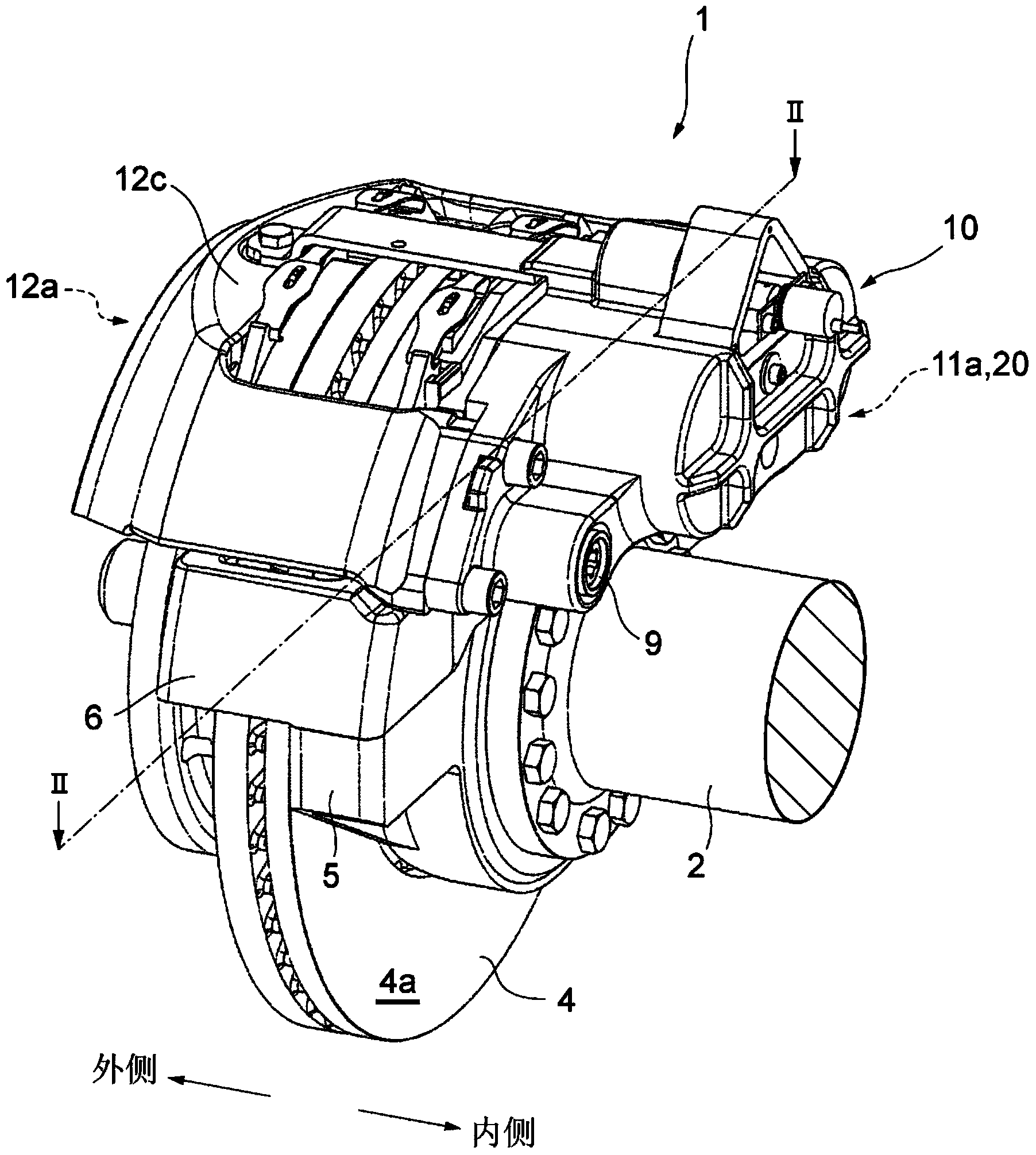
[0033] A description will be given below of an embodiment for carrying out the invention with reference to the drawings. figure 1 A perspective view of a disc brake device 1 as an example to which the present invention is applied is shown. First, refer to Figure 1 to Figure 7 A description is given of the overall configuration of the disc brake device 1 . Note that in the description given below, the outer side in the left-right direction of the vehicle is referred to as the outer side, and conversely, the inner side in the left-right direction of the vehicle is referred to as the inner side.

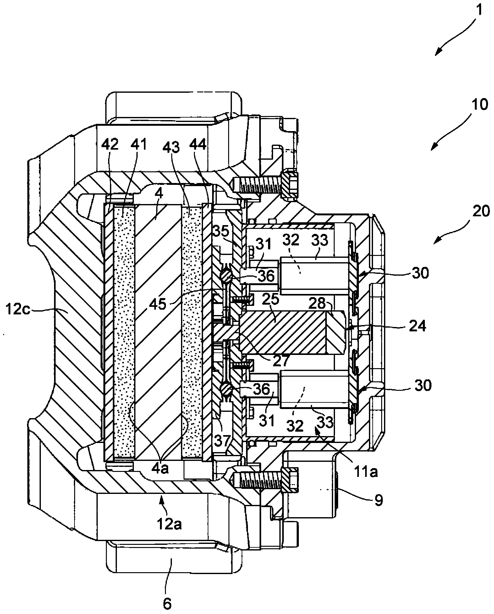
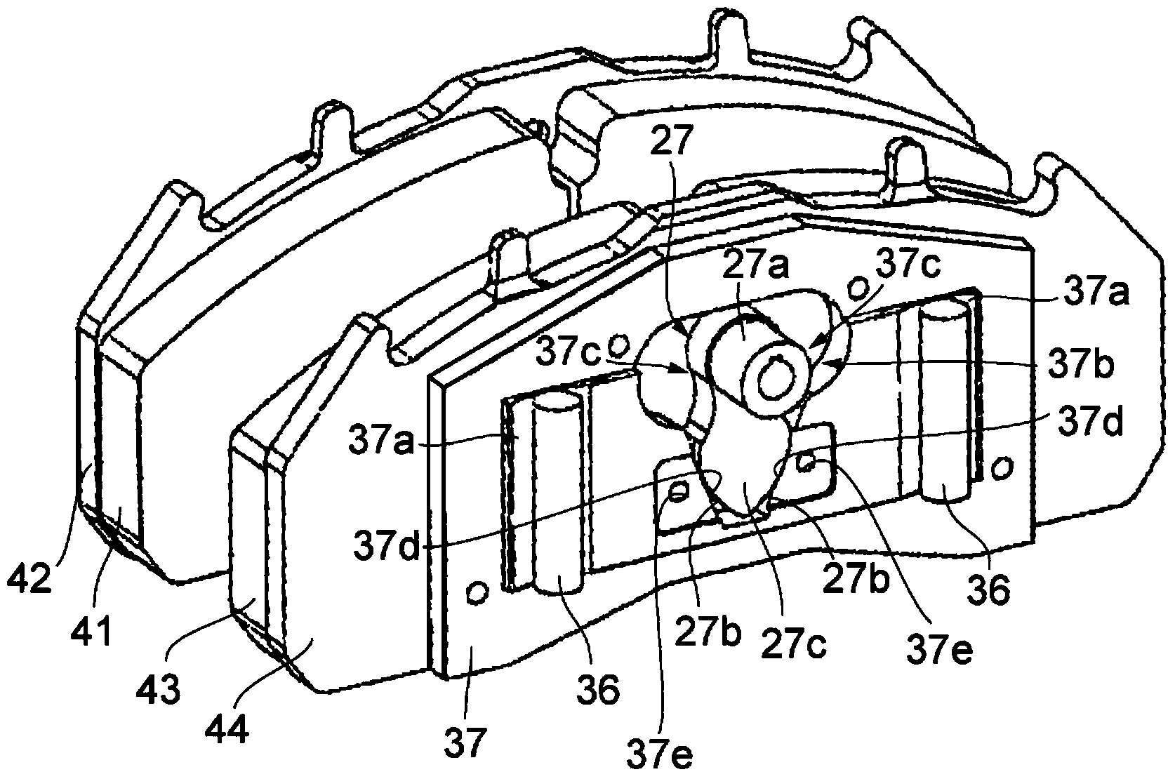
[0034] Such as figure 1 and figure 2 As shown, in the disc brake device 1, the caliper assembly 10 configured by accommodating the inner unit 20 in the inner space 11a on the inner side and housing the inner pad 43 and the outer pad 41 in the opening 12a on the outer side is arranged in Both sides of the caliper assembly 10 hold the ends of the rotor 4 formed into a disk shape. ...


PUM


Abstract

This disk brake device is provided with: a rotor (4) having a braking surface (4a); a caliper; an inner pad (43) and an outer pad positioned facing the braking surface (4a), and a braking operation mechanism which is made to perform a braking operation whereby both pads are pressed against the braking surface (4a). The braking operation mechanism is equipped with a base plate (35), a wedge plate (37) that holds the inner pad (43), a first movement conversion mechanism that moves the wedge plate (37) with respect to the base plate (35), parallel with the braking surface (4a) and in a direction perpendicular to the braking surface (4a) while sliding in the direction of rotation of the rotor (4), ___ an electric motor unit (24) that outputs driving force; and a second movement conversion mechanism that uses the rotational driving force of the electric motor unit (24) to slide the wedge plate (37) parallel to the braking surface (4a) and in the direction of rotation of the rotor (4).

Description

technical field [0001] The present invention relates to a disc brake device used in a vehicle or the like to generate a braking force using friction, and more particularly to a disc brake device configured to use an electric motor as a driving source for generating the braking force. Background technique [0002] Disc brake devices are widely used in vehicles and the like, and are configured to press a pad against a rotor rotating together with a wheel in response to a stepping operation performed on a brake pedal to generate frictional force, and thereby exert friction on the rotor. The rotation is braked. Conventionally known disc brake devices include a type that uses hydraulic force to actuate a piston to press a pad against a rotor and a type that uses compressed air instead of hydraulic force to actuate an operating lever. [0003] For example, in a disc brake device that actuates a piston using hydraulic pressure, such as a booster that amplifies the operating force ...

Claims


Application Information

Patent Timeline
Patent Type & Authority Applications(China)
IPC IPC(8): F16D65/14B60T13/74F16D55/16F16D65/18F16D65/66
CPCB60T13/741F16D55/2262F16D65/183F16D2121/04F16D2121/24F16D2123/00F16D2127/10B60T13/74F16D65/095F16D65/097F16D65/14F16D65/18F16D65/66F16D65/62
Inventor 安田圭宏大泽诚人
Owner TBK
Features
  • R&D
  • Intellectual Property
  • Life Sciences
  • Materials
  • Tech Scout
  • Unparalleled Data Quality
  • Higher Quality Content
  • 60% Fewer Hallucinations
Learn More