
Leaf spring and electric connector

A technology of electrical connectors and leaf springs, applied in the field of leaf springs, can solve the problems of affecting the life of plugging and unplugging, easy deformation, poor overcurrent capability of electrical connectors, etc.

Inactive Publication Date: 2014-01-29
北京格林吉能源科技有限公司
View PDF4 Cites 4 Cited by
  • Summary
  • Abstract
  • Description
  • Claims
  • Application Information

AI Technical Summary

Problems solved by technology

The contact between the leaf spring and the plug is a small round surface, the contact area is limited, the overcurrent capability of the electrical connector is poor, and the arc surface of the arc plate is easy to deform, which affects the plug-in life

Method used


Image

  • Leaf spring and electric connector
  • Leaf spring and electric connector
  • Leaf spring and electric connector

Examples


Embodiment Construction

[0026] Specific embodiments of the present invention will be described in detail below in conjunction with the accompanying drawings.

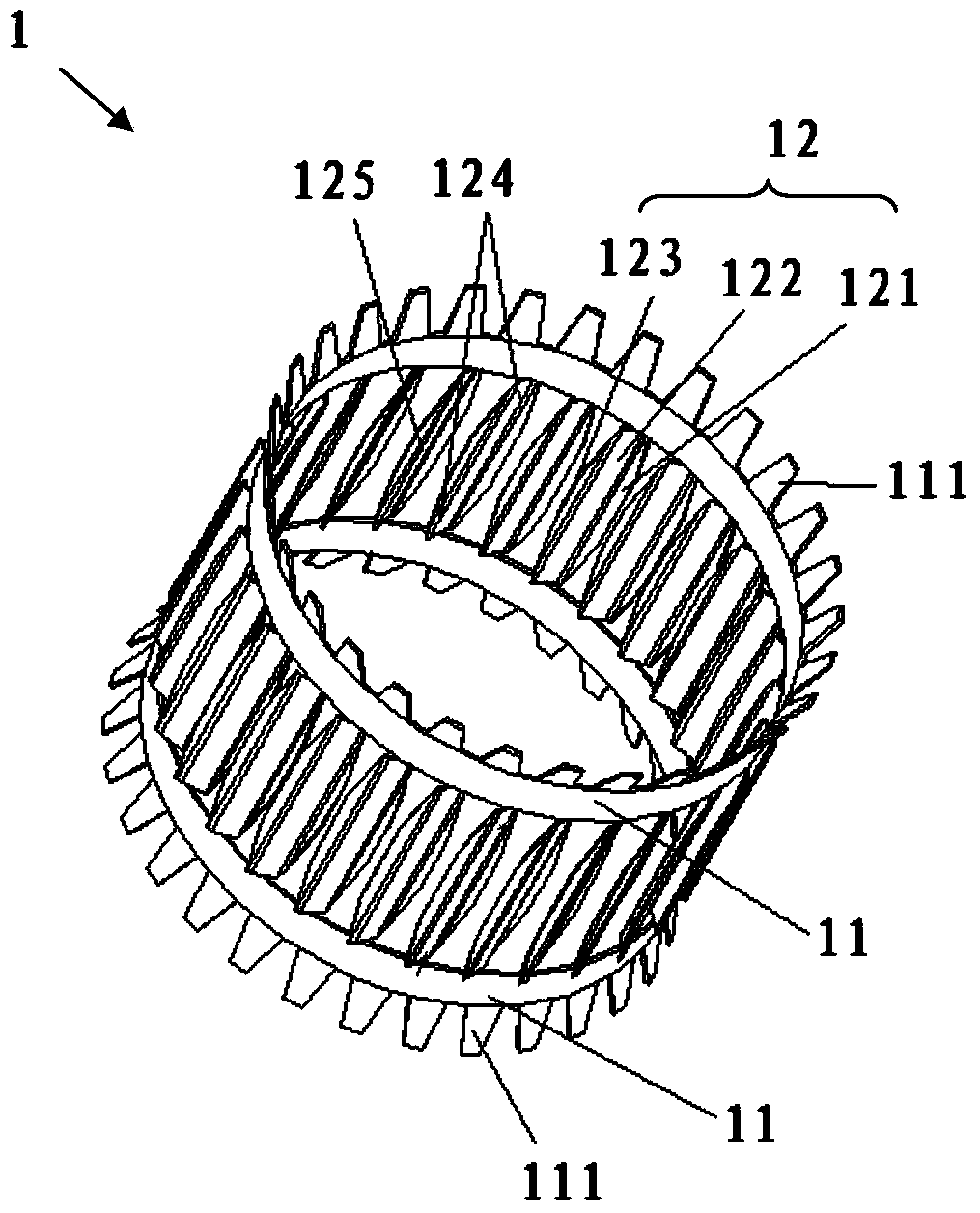
[0027] Such as Figure 3-5 As shown, the leaf spring 1 includes two connecting plates 11 and a plurality of elastic sheets 12, and the elastic sheets 12 include an inner contact plate 121, a transition plate 122, and an outer contact plate 123 connected in sequence, and the two ends of the transition plate 122 are connected to the two connecting plates respectively. 11 is fixedly connected, there is a distance between adjacent two elastic pieces 12 (that is, adjacent two elastic pieces do not touch), the first circumferential surface 126 where the inner contact plate 121 of each elastic piece 12 is located, and the first circumferential surface 126 where the outer contact plate 123 of each elastic piece 12 is located. The two circumferential surfaces 127 are arranged coaxially. The leaf spring 1 can be manufactured by stamping integral moldin...


PUM


Abstract

The invention provides a leaf spring. The leaf spring comprises two connecting plates and a plurality of elastic pieces. Each elastic piece comprises an inner contact plate, a transition plate and an outer contact plate which are connected in sequence, wherein the two ends of the transition plate are fixedly connected with the two connecting plates respectively, a space exists between every two adjacent elastic pieces, and the first circumferential face where the inner contact plates of all the elastic pieces are located and the second circumferential face where the outer contact plates of all the elastic pieces are located are coaxially arranged. The leaf spring increases the conductive contact area, and has better current passing capacity.

Description

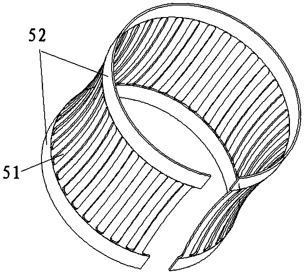
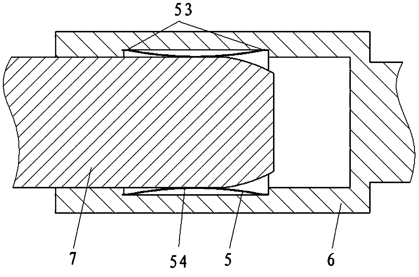
technical field [0001] The invention relates to an electrical connector, in particular to a leaf spring for the electrical connector. Background technique [0002] Existing electrical connectors include plugs, sockets, and leaf springs. Such as figure 1 As shown, the existing leaf spring 5 is a sleeve with a concave shape in the middle of the peripheral surface. The leaf spring 5 is composed of a plurality of arc-shaped plates 51 and two connecting plates 52, and the two connecting plates 52 are respectively located on each arc-shaped plate 51. Two adjacent arc-shaped plates 51 have a fixed distance at both ends. [0003] Such as figure 2 As shown, the leaf spring 5 is located between the plug 7 and the socket 6 , the central recess of the leaf spring 5 contacts the plug 7 , and the connecting plates 52 at both ends of the leaf spring 5 contact the socket 6 . The sizes of the first contact surface 53 between the connecting plate 52 and the socket 6 and the second contac...

Claims


Application Information

Patent Timeline
Patent Type & Authority Applications(China)
IPC IPC(8): H01R13/24H01R13/187
Inventor 陈春辉
Owner 北京格林吉能源科技有限公司
Learn More