High-frequency switching power supply transformer

A high-frequency switching power supply and transformer technology, applied in the direction of transformer/inductor cooling, transformer/inductor parts, transformer/inductor coil/winding/connection, etc., to achieve matching optimization, heat dissipation improvement, and heat reduction effects

Active Publication Date: 2016-04-06
赖永明
View PDF9 Cites 1 Cited by
  • Summary
  • Abstract
  • Description
  • Claims
  • Application Information

AI Technical Summary

Problems solved by technology

The existing problems are: 1) The cross-section of the semi-cylindrical section and the over-current section of the radiator form a sudden change, and the current density of the 5.1N and 5.2N sections of the semi-circular central column tends to increase, and heat is generated there
2) Due to structural reasons, the heat dissipation between the two semicircular columns is poor
Due to the skin effect and eddy current effect, the semi-circular center column passing through the iron core is seriously heated, especially at the 5.1M of the upper end surface, the contact cross-sectional area cannot be increased, and the current density of the contact surface is much higher than the 4N current density of the radiator seat.
When a large current is passed, the fastening surface of the end screw will generate heat for a long time to form a small gap, which will further intensify the heat generation and form a vicious circle, and finally generate micro-sparks to ablate the end face, resulting in poor contact, increased contact resistance, and increased transformer loss

Method used


Image

  • High-frequency switching power supply transformer
  • High-frequency switching power supply transformer
  • High-frequency switching power supply transformer

Examples


Embodiment Construction

[0020] The composition of the high-frequency switching power supply transformer of this embodiment will be described below with reference to the accompanying drawings.

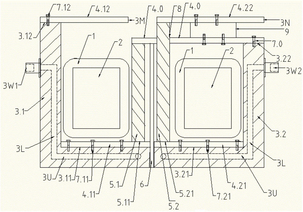
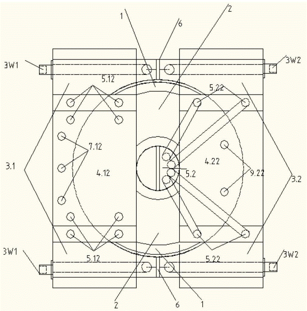
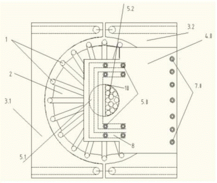
[0021] 1) see figure 1 , figure 2 , a left sheath 3.1 and a right sheath 3.2 made of copper and aluminum alloy are provided, and an insulating layer formed of high thermal conductivity silica gel 6 is formed between the two sheaths. See figure 1 , except that the left top surface 3.12 of the left sheath is higher than the right top surface 3.22 of the right sheath, the two sheaths have the same structural shape and size. Here, the left sheath 3.1 is taken as an example for illustration. See Figure 5 , The left sheath 3.1 is a rectangle with an equal-diameter semicircular cavity, a left base 3A with a semicircular left bottom surface 3.11; a semi-cylindrical 3B with a left top surface 3.12. A connected horizontal U-shaped water pipe 3U and two L-shaped water pipes 3L in the semi-cylinder are arranged i...


PUM


Abstract

The present invention provides a high-frequency switching power supply transformer. The high-frequency switching power supply transformer is provided with a left protective sleeve and a right protective sleeve which are electrically and thermally conductive. An annular iron core winding a primary side coil is disposed in an inner circular cavity which is filled with silica gel and which is formed by the two protective sleeves. Two insulated high-frequency electromagnetic twisted wires formed by twisting multiple enameled wires are disposed inside a middle hole of the iron core. An upper end and a lower end of each of the two twisted wires are fixed on upper and lower copper bars of the two coils respectively, by welding or pressing. Moreover, a left upper copper bar and a tapping copper bar are fixed on top surfaces of the left and right protective sleeves respectively, and two lower copper bars are fixed on bottom surfaces of the two protective sleeves respectively to form a secondary side. The enameled wires effectively eliminate heat caused by a skin effect or an eddy current effect, and improve an over-current capability and reliability; and power is increased and the volume is reduced. The highly thermally conductive silica gel absorbs heat and rapidly transfers the heat to the protective sleeves internally cooled by water, thereby greatly improving heat dissipation. According to the high-frequency switching power supply transformer, problems of heat and great loss of a transformer discloses by Projects from National Natural Foundation Fund are solved; efficiency can be easily improved; and matching can be optimized. The high-frequency switching power supply transformer is used for low-voltage large-current half-wave, full-wave and single-phase rectification in electrolysis, electric heating, electric vehicles and the like.

Description

[0001] (1) Technical field: High-frequency switching power supply transformers, generally used in the production of low-voltage, high-current, high-frequency switching power supply transformers in industries such as polysilicon, electroplating, electrolysis, and electric vehicle charging. It belongs to transformer class (H01F). (2) Background technology [0002] For the principle and structure of existing low-voltage, high-current, and high-frequency rectifier transformers, see Figure 6-Figure 8 . See Figure 6 , The primary coil 1 is wound on the annular iron core 2, and the secondary coil 3 of the transformer is one turn, which is generally formed by adding a conductive base through the middle column of the iron core. Secondary side formation: see Figure 6 , using two coils in series, 3.1N, 3.2N, with a center tap of 30 points, to form two branches connected in parallel with rectifier diodes in series. The two currents on the secondary side are i31 and i32 respectively;...

Claims


Application Information

Patent Timeline
Patent Type & Authority Applications(China)
IPC IPC(8): H01F27/28H01F27/22H01F27/16H01F27/29H01F27/30
CPCH01F27/16H01F27/22H01F27/28H01F27/2895H01F27/29H01F27/306
Inventor 赖永明张成胡云贵
Owner 赖永明
Why Eureka
Try Eureka