Coupling capacitor

A coupling capacitor and electrode technology, which is applied in the field of coupling capacitors, can solve problems such as unsatisfactory use requirements, high high-frequency loss, and poor stability, and achieve the effects of stable and reliable practicability, low high-frequency loss, and strong overcurrent capability

Inactive Publication Date: 2015-10-07
蒋玲
View PDF2 Cites 1 Cited by
  • Summary
  • Abstract
  • Description
  • Claims
  • Application Information

AI Technical Summary

Problems solved by technology

In addition, the Chinese patent literature also discloses another capacitor [application number: 201020698211.4], which includes a body, a sleeve, an end cover and a terminal, one end of the sleeve is sleeved on the body, and the other end of the sleeve is connected to the end cover , the connection terminal is connected to the body and protrudes out of the end cover. It is characterized in that: there is also a barbed piece between the body and the sleeve, and the barbed piece includes a plug and a plug connected to the plug. An elastic piece is provided, one end of the elastic piece is connected to the plug, the other end of the elastic piece is turned outward toward the outside of the insertion piece, and the inner cavity of the sleeve is provided with a socket that can be matched with the plug; the two sides of the insertion piece There are multiple barbs arranged at intervals. The above two solutions have improved the existing technology to a certain extent, but the capacitors here have complex structures, and still have disadvantages such as poor stability and high high-frequency loss, which cannot meet the requirements of use.

Method used


Image

  • Coupling capacitor

Examples


Embodiment Construction

[0012] The present invention will be described in further detail below in conjunction with the accompanying drawings and specific embodiments.

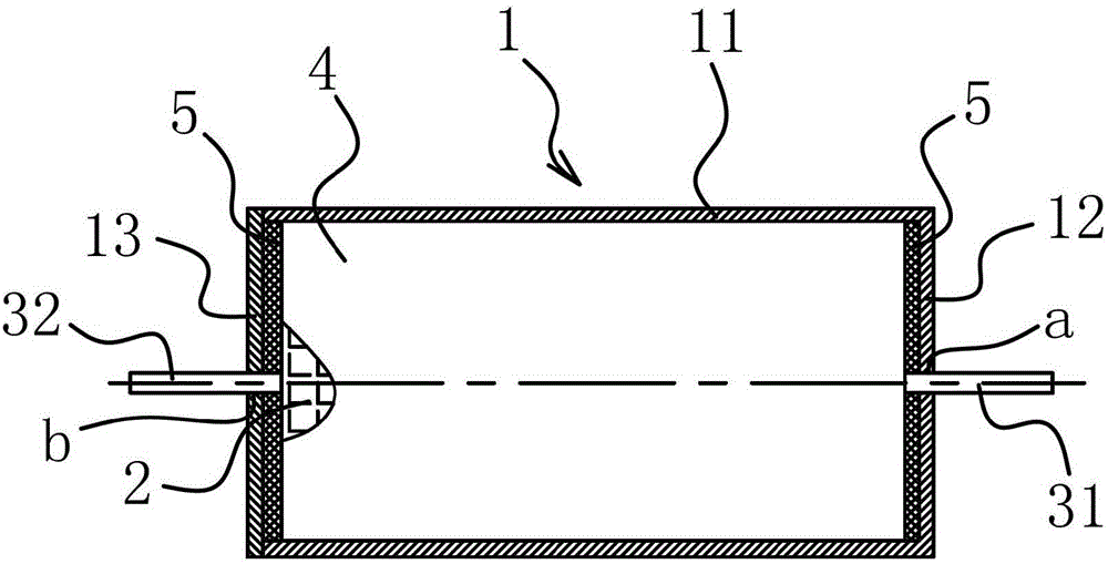
[0013] like figure 1 As shown, the coupling capacitor includes a cylindrical metal case 1, the metal case 1 is any one of oval and circular, and a winding core 2 is arranged inside the metal case 1, and the winding core 2 One end is provided with the first electrode 31 whose end extends to the outside of the winding core 2, and the other end is provided with the second electrode 32 whose end extends to the outside of the winding core 2, and the winding core 2 is provided with The Mylar tape layer 4 wrapped outside the winding core 2, the metal casing 1 is provided with a potting layer 5 between one end and the winding core 2, and between the other end and the winding core 2, The metal casing 1 includes a cylindrical body 11 with one end open, and the other end has a shell bottom 12. The cylindrical body 11 and the shell bottom 12 are...


PUM


Abstract

The invention belongs to the capacitor technology field, and especially relates to a coupling capacitor. The technical problems are solved that present technical design is not reasonable and stability is poor. The coupling capacitor comprises a cylindrical metal housing. A winding core is arranged in the metal housing. A first electrode with an end part extending out from the winding core is arranged at one end of the winding core, and a second electrode with an end part extending out from the winding core is arranged at the other end of the winding core. The coupling capacitor is characterized in that an adhesive tape layer coating the winding core is arranged on the winding core. Filling packaging layers are arranged between one end of the metal housing and the winding core and between the other end and the winding core respectively. Compared with the prior art, the coupling capacitor is advantageous in that practicality is strong, the coupling capacitor is stable and reliable, the high-frequency loss is small, the over-current capability is strong, the temperature drift is small, and the temperature of the whole capacitor is low.

Description

technical field [0001] The invention belongs to the technical field of capacitors, in particular to a coupling capacitor. Background technique [0002] Coupling capacitors are mainly used in inverter welding machines, inverter power supplies, electroplating power supplies, and other power electronic equipment coupling DC blocking occasions. With the rapid development of electronic information technology, the replacement speed of digital electronic products is getting faster and faster. The production and sales of consumer electronic products, mainly flat-screen TVs, notebook computers, digital cameras and other products, continue to grow, which drives the growth of the capacitor industry. It is a device that stores charge and electric energy composed of electrodes made of two conductors that are close to each other and insulated from each other. Capacitors are one of the electronic components widely used in electronic equipment, and are widely used in DC blocking, coupling, ...

Claims


Application Information

Patent Timeline
IPC IPC(8): H01G2/10H01G2/02
Inventor 蒋玲
Owner 蒋玲
Why Eureka
Try Eureka